






電控玻璃特點與優勢
調光ガラスの特長とメリット
Features & Advantages
- 白色或深灰色不透明屏障,輕觸開關後即可轉為透明狀態
- 結合建築師 / 設計師 / 承包商的創造性設計理念,工程靈活度高
- 可製成圓弧、異形或穿孔造型,滿足客製化需求
- 靈活的尺寸 — 最大 1,500 mm × 3,500 mm
- 可設計單層或複層玻璃結構
- 可用在特殊形狀(圓形、三角形、多邊形)玻璃窗上
- 高對比背投螢幕的絕佳解決方案
- 可阻擋 99% 的紫外線
- 低工作電壓,每平方米消耗不到 5W
- 謹慎使用時有 25 年的平均使用壽命
- ホワイトまたはダークグレーの不透明スクリーンが、スイッチ操作ひとつで透明に切り替わります
- 建築家・デザイナー・施工業者の創造的な設計意図に対応し、施工の自由度が高い
- 円弧・異形・穴あけ加工が可能で、オーダーメイドのご要望に対応
- 柔軟なサイズ対応 — 最大 1,500 mm × 3,500 mm
- 単板・複層いずれのガラス構成にも設計可能
- 特殊形状(円形・三角形・多角形)のガラス窓にも使用可能
- 高コントラストのリアプロジェクションスクリーンとしても最適
- 紫外線を 99% カット
- 低駆動電圧、消費電力は 1 m² あたり 5W 未満
- 日常的なご使用において 10 年以上の使用強度に対応します
- White or dark grey opaque barrier — switches to transparent at the flick of a switch
- Highly flexible — works with creative design ideas from architects, designers, and contractors
- Can be cut into curves, irregular shapes, or with perforations for customised needs
- Flexible sizing — up to 1,500 mm × 3,500 mm
- Available as single-pane or double-glazed structures
- Works on special shapes (circles, triangles, polygons)
- Excellent solution for high-contrast rear-projection screens
- Blocks up to 99% of UV radiation
- Low operating voltage — under 5 W per square metre
- Average service life of 25 years with proper use
技術原理
技術原理
How It Works
電源關閉時,液晶分子隨機排列,阻擋光源 → 電控玻璃呈現不透明。
電源開啟後,液晶分子排列有序,光線得以通過 → 電控玻璃變得透明。
電源が切れているとき、液晶分子はランダムに配列して光を遮ります → 調光ガラスは不透明になります。
電源を入れると、液晶分子が規則的に配列して光が通過します → 調光ガラスは透明になります。
When power is off, the liquid-crystal molecules align randomly, blocking light → the glass appears opaque.
When power is on, the molecules line up in an orderly fashion, allowing light to pass → the glass becomes transparent.
技術規格
技術仕様
Technical Specifications
| 玻璃顏色 | 可與彩色膜或各種有色玻璃結合,以滿足各種客製化需求 搭配灰玻、茶玻等有色玻璃時,直貼式與膠合式的呈色不同,請見第 5 章「色差提醒(批次與結構)」。 |
|---|---|
| 厚度 | 8.6 mm、10.6 mm、11.2 mm,及複層結構 |
| 尺寸 |
STARTEK 1 系列:最大 4,500 mm × 2,000 mm 明基(BenQ)系列(PDLC 95 / 97 / 98):最大 1,500 mm × 3,000 mm 註:兩條產品線最大尺寸不同,設計分割時請依實際使用之系列確認上限。明基系列另有上游材料技術操作手冊(工作電壓 48 VAC、矽利康指定品牌、貼膜流程等),由 STARTEK 內部工程團隊執行,本文件不涵蓋。
|
| 形狀 | 任何形狀或彎曲,包括開孔 |
| 環境 | 儲存:-15°C 至 60°C / 工作溫度:-20°C 至 60°C |
| 電氣 | 驅動電壓 65 VAC(提供變壓器)/ 電流 200 mA / m² / 功率 5 W / m² |
| 切換時間 | 室溫下約 < 10 ms |
| 光學 | 可見光透射率:約 75% ~ 80%(開啟狀態)/ 可視角 > 140° |
| 壽命 | 依據本規格書儲存與安裝、正確使用:室內 25 年 |
| ガラスの色 | カラーフィルムや各種の色ガラスとの組み合わせが可能で、さまざまなオーダーメイドのご要望に対応します グレーガラス・ブロンズガラスなどの色ガラスと組み合わせる場合、直貼り式と合わせ式では発色が異なります。第 5 章「色差に関する注意(ロット・構造)」をご参照ください。 |
|---|---|
| 厚み | 8.6 mm、10.6 mm、11.2 mm、および複層構成 |
| 寸法 |
STARTEK 1 シリーズ:最大 4,500 mm × 2,000 mm 明基(BenQ)シリーズ(PDLC 95 / 97 / 98):最大 1,500 mm × 3,000 mm 注:2 つの製品ラインで最大寸法が異なります。割付を設計される際は、実際にご使用になるシリーズの上限をご確認ください。明基シリーズには別途、上流材料メーカーの技術取扱マニュアル(駆動電圧 48 VAC、シーリング材の指定ブランド、フィルム貼付手順など)があり、STARTEK 社内のエンジニアリングチームが実施します。本書ではその内容を扱いません。
|
| 形状 | あらゆる形状・曲面に対応(穴あけを含む) |
| 環境 | 保管:-15°C 〜 60°C / 動作温度:-20°C 〜 60°C |
| 電気 | 駆動電圧 65 VAC(トランス付属)/ 電流 200 mA / m² / 消費電力 5 W / m² |
| 切替時間 | 常温で約 < 10 ms |
| 光学 | 可視光透過率:約 75% 〜 80%(通電時)/ 視野角 > 140° |
| 寿命 | 本仕様書に従って保管・施工し、正しくご使用いただいた場合:屋内で 10 年以上の使用強度に対応 |
| Glass Colour | Can be combined with colour films or tinted glass for various custom requirements With tinted glass such as grey or bronze, self-adhesive and laminated products read differently — see Section 5, "Colour Variation Note". |
|---|---|
| Thickness | 8.6 mm, 10.6 mm, 11.2 mm, and laminated/insulated structures |
| Size |
STARTEK 1 Series: up to 4,500 mm × 2,000 mm BenQ Series (PDLC 95 / 97 / 98): up to 1,500 mm × 3,000 mm Note: Maximum sizes differ between the two product lines. Confirm against the actual series used when planning panel divisions. The BenQ series has a separate upstream technical handbook (48 VAC operating voltage, specified silicone brands, lamination process) executed by STARTEK's internal engineering team and not covered here.
|
| Shape | Any shape or curve, including cutouts |
| Environment | Storage: −15°C to 60°C / Operating: −20°C to 60°C |
| Electrical | Drive voltage 65 VAC (transformer included) / Current 200 mA/m² / Power 5 W/m² |
| Switching Time | ≈ < 10 ms at room temperature |
| Optical | Visible light transmittance ≈ 75–80% (ON state) / Viewing angle > 140° |
| Lifespan | 25 years indoors when stored, installed, and used according to this specification |
使用須知
ご使用上の注意
Usage Notes
- STARTEK 提供基本 5 年或延長最長 10 年(依報價規定)的保固計畫。
- 為了維持壽命,建議使用上 24 小時內至少 4 ~ 5 小時處於「關閉」狀態,且一次不得連續「打開」超過 20 小時。
- 電控玻璃在光學上不如一般玻璃透明,由於物質不滅律會出現一定程度的霧狀,不應視為品質問題而要求更換或退款。
- STARTEK は標準 5 年、または最長 10 年までの延長保証プラン(お見積り記載の条件による)をご提供します。
- 寿命を維持するため、24 時間のうち少なくとも 4 〜 5 時間は「OFF」の状態とし、連続して 20 時間を超えて「ON」にしないことをお勧めします。
- 調光ガラスは光学的に通常のガラスほど透明ではなく、物質の性質上ある程度のヘイズ(曇り)が生じます。これを品質不良として交換または返金をご請求いただくことはできません。
- STARTEK offers a standard 5-year warranty, extendable up to 10 years (per quotation terms).
- To preserve lifespan, the glass should be OFF for at least 4–5 hours within any 24-hour period, and should not be kept continuously ON for more than 20 hours at a stretch.
- Smart glass is not optically as clear as ordinary glass. Due to its functional materials, a slight haze is inherent in the ON state and does not constitute grounds for replacement or refund.
尺寸公差(合約條款)
寸法公差(契約条項)
Dimensional Tolerance (Contract Terms)
- 電控液晶導電膜尺寸會比玻璃長寬 -2 ~ 5 mm,電極區約 15 mm 內,並會在膜邊使用收邊材料或防水膠以確保使用年限。
- 依據現場實際狀況,玻璃長寬可容許正負 3 公分標準差,此不為退/換貨之理由。
- 本產品依照 CNS-1183 膠合玻璃進行驗收尺寸、外觀等標準(玻璃含有氣泡、雜質應在 CNS-2441、2442、3288 所規定容許數之合計值以下)。
- 調光フィルムの寸法はガラスより縦横それぞれ -2 〜 5 mm 小さくなり、電極部は約 15 mm 以内です。使用年数を確保するため、フィルム端部には端末処理材または防水シール材を使用します。
- 現場の実状に応じて、ガラスの縦横寸法に±3 cm の標準公差を許容します。これを理由とする返品・交換はお受けできません。
- 本製品は CNS-1183(合わせガラス)に基づき、寸法・外観などの検収基準を適用します(ガラス内の気泡・異物は CNS-2441、2442、3288 に規定される許容数の合計値以下とします)。
- The PDLC film is 2–5 mm smaller in both length and width than the glass, with an electrode area of up to ~15 mm, and edge-sealing material or waterproof adhesive is applied at the film edge to protect service life.
- Depending on site conditions, glass length and width may vary by ±3 cm, which does not constitute grounds for return or exchange.
- This product is inspected for size and appearance per CNS-1183 (laminated glass). Bubbles and impurities are accepted within the limits of CNS-2441, 2442, and 3288.
電控玻璃形狀(可加工、鑽孔)
調光ガラスの形状(加工・穴あけ対応)
Shapes & Cutouts
電控玻璃支援各種幾何形狀加工與鑽孔,含矩形、圓形、三角形、梯形、平行四邊形、圓弧頂、缺口、開孔、切口、特殊形狀。
調光ガラスは各種の幾何形状への加工と穴あけに対応します。長方形、円形、三角形、台形、平行四辺形、アーチ頂部、切欠き、開口、スリット、特殊形状などが可能です。
Smart glass supports a wide range of geometric shapes and drilling — including rectangles, squares, triangles, trapezoids, parallelograms, domed tops, notches, holes, cut-outs, and special shapes.
電控玻璃形式
調光ガラスの種類
Product Types
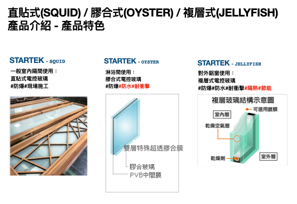
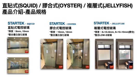
STARTEK 提供三種型式以對應不同空間情境:直貼式(SQUID)、膠合式(OYSTER)、複層式(JELLYFISH)。
STARTEK では、空間の用途に応じた 3 つのタイプをご用意しています:直貼り式(SQUID)、合わせ式(OYSTER)、複層式(JELLYFISH)。
STARTEK offers three product types matched to different spatial scenarios: self-adhesive (SQUID), laminated (OYSTER), and insulated double-glazed (JELLYFISH).
直貼式
- 厚度 8 mm、10 mm
- 整合優白強化玻璃
- 現場施工
膠合式
- 厚度 10 mm、12 mm
- 雙層特殊超透膠合膜 + EVA 中間膜
- 整合優白強化玻璃
複層式
- 厚度 8+12+8、8+12+10(膠合)
- 整合 LOW-E 玻璃,可選用鍍膜
- 內含乾燥空氣層 + 乾燥劑
直貼り式
- 厚み 8 mm、10 mm
- 高透過強化ガラスと一体化
- 現場施工
合わせ式
- 厚み 10 mm、12 mm
- 2 層の特殊高透過ラミネートフィルム + EVA 中間膜
- 高透過強化ガラスと一体化
複層式
- 厚み 8+12+8、8+12+10(合わせ)
- LOW-E ガラスと一体化、コーティング選択可
- 乾燥空気層 + 乾燥剤を内蔵
Self-Adhesive
- Thickness 8 mm, 10 mm
- Integrated with low-iron tempered glass
- On-site installation
Laminated
- Thickness 10 mm, 12 mm
- Dual-layer ultra-clear laminate + EVA interlayer
- Integrated with low-iron tempered glass
Insulated (IGU)
- Thickness 8+12+8, 8+12+10 (laminated)
- Integrated with LOW-E glass; coating options available
- Internal dry-air cavity + desiccant
產品形式參考圖
製品タイプ参考図
Product Type Reference
SQUID 直貼式加工程序
SQUID 直貼り式の加工手順
SQUID Self-Adhesive — Fabrication Process
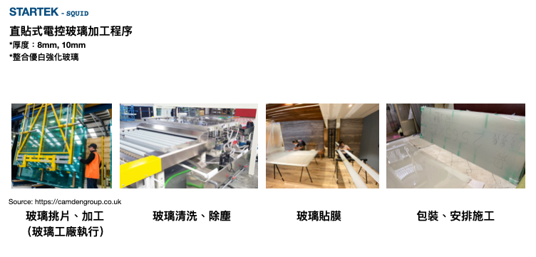
玻璃挑片 / 加工(玻璃工廠執行)→ 玻璃清洗、除塵 → 玻璃貼膜 → 包裝、安排施工
ガラスの選別 / 加工(ガラス工場にて実施)→ ガラスの洗浄・除塵 → フィルム貼付 → 梱包・施工手配
Glass selection & processing (at the glass factory) → cleaning & dust removal → film application → packaging & installation scheduling
產品比較表
製品比較表
Product Comparison
| 項目 | SQUID 直貼式 | OYSTER 膠合式 | JELLYFISH 複層式 |
|---|---|---|---|
| 既有玻璃可施作 | △ 須先確認玻璃平整度、施作環境 | ✗ | ✗ |
| 電線佈線 | 依現場狀況,適用合適收邊條 | 可藏在框內 | △ 可藏在框內 |
| 局部施作 | ○ | ✗ | 不一定,視不同組合決定 |
| 潮濕處使用 | ✗ | ○ | ○ |
| 接縫 | 接縫約 5–7 mm,會透光 | 無框施作(絕對玻對玻)須加修飾條收邊 1.5 cm | 無框施作(絕對玻對玻)須加修飾條收邊 2 cm |
| 隔熱 / 節能 | ✗ | ✗ | ○ |
| 隔音 | ○ | ○ | ○ |
| 兩面觀感一致性 搭配有色玻璃時 | 兩面略有差異:貼膜面顏色較淺、略帶白 | 兩面接近一致:皆先透出玻璃本色 | 視組合而定,請於設計階段確認 |
| 項目 | SQUID 直貼り式 | OYSTER 合わせ式 | JELLYFISH 複層式 |
|---|---|---|---|
| 既存ガラスへの施工 | △ ガラスの平滑度・施工環境の事前確認が必要 | ✗ | ✗ |
| 配線 | 現場状況に応じ、適切な見切り材を使用 | フレーム内に隠蔽可能 | △ フレーム内に隠蔽可能 |
| 部分施工 | ○ | ✗ | 組み合わせにより異なる |
| 湿潤環境での使用 | ✗ | ○ | ○ |
| 目地 | 目地は約 5〜7 mm、光が透けます | フレームレス施工(ガラス突付け)では 1.5 cm の見切り材が必要 | フレームレス施工(ガラス突付け)では 2 cm の見切り材が必要 |
| 断熱 / 省エネ | ✗ | ✗ | ○ |
| 遮音 | ○ | ○ | ○ |
| 両面の見え方の一致 色ガラスと組み合わせた場合 | 両面でやや差が出ます:フィルム貼付面は色が薄く、やや白みを帯びます | 両面ほぼ一致:いずれもガラス本来の色が先に見えます | 組み合わせにより異なるため、設計段階でご確認ください |
| Item | SQUID Self-Adhesive | OYSTER Laminated | JELLYFISH Insulated |
|---|---|---|---|
| Application on existing glass | △ Check flatness & site conditions first | ✗ | ✗ |
| Wiring | Depends on site; concealed via edge trim | Concealed inside frame | △ Concealed inside frame |
| Partial application | ○ | ✗ | Depends on configuration |
| Use in wet areas | ✗ | ○ | ○ |
| Seam | 5–7 mm seam, light leaks through | Frameless install (glass-to-glass) needs 1.5 cm trim | Frameless install (glass-to-glass) needs 2 cm trim |
| Thermal insulation / energy saving | ✗ | ✗ | ○ |
| Acoustic insulation | ○ | ○ | ○ |
| Colour match between the two faces with tinted glass | Slightly different: the filmed face looks lighter, with a whitish cast | Close to identical: both faces read the glass tint first | Depends on configuration; confirm at design stage |
膠合式(OYSTER)邊緣漏光提醒
合わせ式(OYSTER)のエッジ漏光に関する注意
Edge Light-Gap Note (OYSTER Laminated)

色差提醒(批次與結構)
色差に関する注意(ロット・構造)
Colour Variation Note (Batch & Structure)
- 直貼式(SQUID)—— 調光膜貼在玻璃單面,貼膜面看起來顏色較淺、略帶白,另一面則透出玻璃本色,兩面觀感不一致。以灰玻為例,貼膜面偏淺白。
- 膠合式(OYSTER)—— 調光膜夾在兩片玻璃中間,兩面都先透出玻璃本色,因此兩面顏色接近一致;整體顏色比直貼式更深,灰玻膠合會帶一點茶色感。
- 直貼り式(SQUID)—— 調光フィルムをガラスの片面に貼るため、貼付面は色が薄く、やや白みを帯びて見え、もう一方の面はガラス本来の色が透けます。両面の見え方が一致しません。グレーガラスの場合、貼付面は淡く白っぽくなります。
- 合わせ式(OYSTER)—— 調光フィルムを 2 枚のガラスで挟むため、両面ともガラス本来の色が先に見え、両面の色がほぼ一致します。全体の色は直貼り式より濃く、グレーガラスの合わせではやや茶色みを感じます。
- SQUID (self-adhesive) — the film is applied to one face, so the filmed side appears lighter with a whitish cast while the opposite side reads the glass tint. The two faces do not match. On grey glass, the filmed side looks pale and washed out.
- OYSTER (laminated) — the film sits between two glass panes, so both faces read the glass tint first and look close to identical. The overall colour is deeper than self-adhesive; laminated grey glass takes on a slightly bronze cast.
電控玻璃安裝
調光ガラスの施工
Installation
基本條件
基本条件
Site Prerequisites
- 確認現場及工作區域條件,所有不利情況皆以調整後,才開始進行施工。
- 準備好電控玻璃後,需確認運送通道暢通,沒有可能影響工作的障礙物。
- 去除安裝場域可能影響矽利康收尾的污染或阻礙物。
- 上矽利康之前,確認已將電控玻璃表面做基礎清潔,並使用明星電控建議品牌矽利康。
- 現場および作業区域の条件を確認し、支障となる事項をすべて是正したうえで施工を開始してください。
- 調光ガラスの準備が整ったら、搬入経路が確保され、作業の妨げとなる障害物がないことを確認してください。
- 施工箇所から、シーリングの仕上げに影響する汚れや障害物を除去してください。
- シーリング施工の前に、調光ガラス表面の基本清掃が済んでいることを確認し、STARTEK 推奨ブランドのシーリング材を使用してください。
- Confirm site and work-area conditions. Resolve all unfavourable conditions before starting work.
- Once the glass is on site, ensure the delivery path is clear and free of obstacles.
- Remove any contamination or obstruction that could affect silicone sealing.
- Before applying silicone, perform a basic surface clean of the glass and use only STARTEK-recommended silicone brands.
安裝
施工
Installation
- 開始安裝之前,先檢查每一塊電控玻璃。
- 不要安裝尺寸不合適、邊緣受損或已經有明顯刮傷、磨損或其他缺陷的產品。
- 在案場負責人驗收前,不要從電控玻璃上移除明星電控提供之標示標籤。
- 遵守所有安裝說明以及現場施工圖規範。
- 以施工圖面規劃固定電控玻璃。
- 電控玻璃之間接縫必須符合明星電控相關規範與標準。
- 當電控玻璃需要安裝在可移動的框架中(如移動窗或滑門),須明確事前指定。
- 電控玻璃在戶外或潮濕的儲放空間中,必須進行包覆,避免直接淋水浸濕。
- 電控玻璃安裝位置須考量電線連接,以便後續接電安裝。
- 在潮濕環境中,電線連接必須要在頂部保持乾燥且絕緣條件下密封。
- 施工を開始する前に、調光ガラスを 1 枚ずつ点検してください。
- 寸法が合わないもの、端部が損傷しているもの、明らかな傷・摩耗・その他の欠陥があるものは施工しないでください。
- 現場責任者による検収が済むまで、STARTEK が貼付した表示ラベルを剥がさないでください。
- すべての施工要領および現場施工図の規定に従ってください。
- 施工図に従って調光ガラスを固定してください。
- 調光ガラス相互の目地は、STARTEK の関連規範および基準に適合させてください。
- 可動フレーム(可動窓や引戸など)への取り付けが必要な場合は、事前に明確にご指定ください。
- 屋外または湿気のある保管場所に置く場合は、直接水がかからないよう養生してください。
- 後の電気接続作業を考慮した位置に施工してください。
- 湿潤環境では、配線の接続部を上部で乾燥・絶縁状態を保ったまま密封してください。
- Inspect every panel before installing.
- Do not install panels with wrong dimensions, damaged edges, or visible scratches, abrasions, or other defects.
- Do not remove STARTEK's identification labels until the site manager has accepted the work.
- Follow all installation instructions and site shop-drawings.
- Fix the glass according to the shop-drawings.
- Seams between panels must comply with STARTEK's specifications and standards.
- If the glass needs to be installed in a movable frame (e.g. sliding window or door), this must be specified in advance.
- If stored outdoors or in damp areas, the glass must be wrapped to prevent direct water exposure.
- Installation location must allow for subsequent electrical connection.
- In damp environments, electrical connections must be sealed at the top under dry, insulated conditions.
保護
養生
Protection
安裝後需至少 24 小時固定,不可隨意觸碰或將其他物體、焊接火花等容易破壞電控玻璃表面材料直接使用。
施工後は最低 24 時間の固定養生期間が必要です。この間はみだりに触れたり、他の物体や溶接火花など、調光ガラスの表面材を損傷させるおそれのあるものを直接当てたりしないでください。
After installation, allow at least 24 hours for the fixings to cure. Avoid contact with objects, welding sparks, or anything that could damage the glass surface.
清潔
清掃
Cleaning
使用潔淨乾布搭配酒精,或其他明星電控推薦之清潔用品擦拭電控玻璃表面即可。直貼式(後貼液晶膜)另有清潔限制 — 清潔劑一律噴在布上局部擦拭,不可整面噴灑,見本章「既有玻璃後貼液晶膜」。
清潔な乾いた布にアルコール、または STARTEK が推奨する洗浄用品を用いて、調光ガラスの表面を拭いてください。直貼り式(後貼り調光フィルム)には別途、清掃上の制限があります —— 洗浄剤は必ず布に吹き付けて部分的に拭き、面全体に直接スプレーしないでください。本章の「既存ガラスへの調光フィルム後貼り」をご参照ください。
Wipe the surface with a clean dry cloth and alcohol, or another STARTEK-recommended cleaning product. Self-adhesive (retrofit film) has an additional restriction — always spray the cleaner onto the cloth and wipe the spot; never spray across the panel. See "Retrofit Film on Existing Glass" in this section.
框架設計/佈線規劃
フレーム設計/配線計画
Frame Design & Wiring Planning
參考明星電控規劃之規範。
STARTEK が定める規範をご参照ください。
Refer to STARTEK's planning specifications.
核心觀念 — 電控玻璃要藏電線
基本の考え方 — 調光ガラスは配線を隠す必要があります
Core Principle — Conceal the Wires
很多設計師第一次接觸電控玻璃時,會以為它「就是一片玻璃」 — 其實不是。電控玻璃有電極、要接電、需要變壓器,圖面上必須像規劃線型 LED 燈具一樣,預留溝槽、二次線、變壓器、110V 插座。
調光ガラスに初めて触れるデザイナーの多くは「ただのガラス 1 枚」と考えがちですが、そうではありません。調光ガラスには電極があり、電源接続が必要で、トランスも必要です。図面上では、ライン照明器具を計画するのと同じように、配線溝、二次側配線、トランス、100V コンセントをあらかじめ確保しておく必要があります。
Many designers approach smart glass as if it were "just a sheet of glass" — it isn't. Smart glass has electrodes, needs power, and requires a transformer. Treat it like a linear LED fixture in your drawings — reserve grooves, run secondary wiring, plan transformer locations, and provide a 110V outlet.
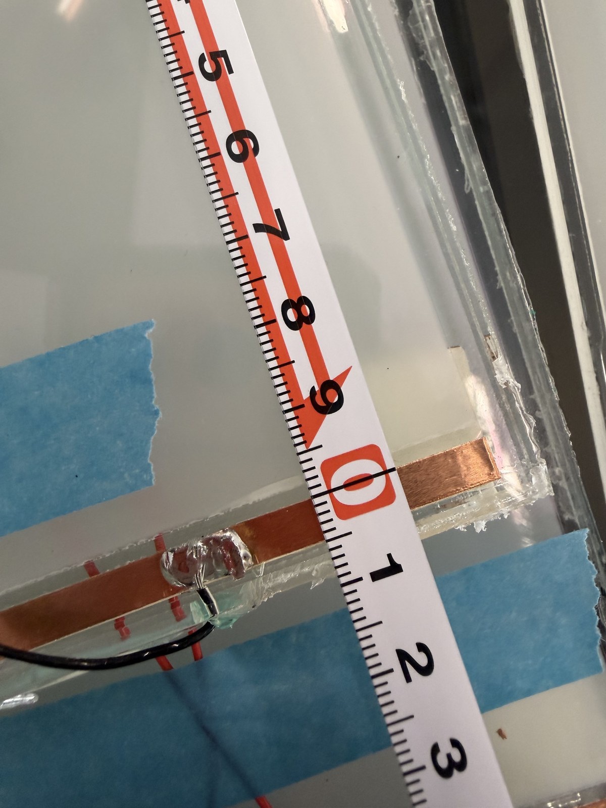
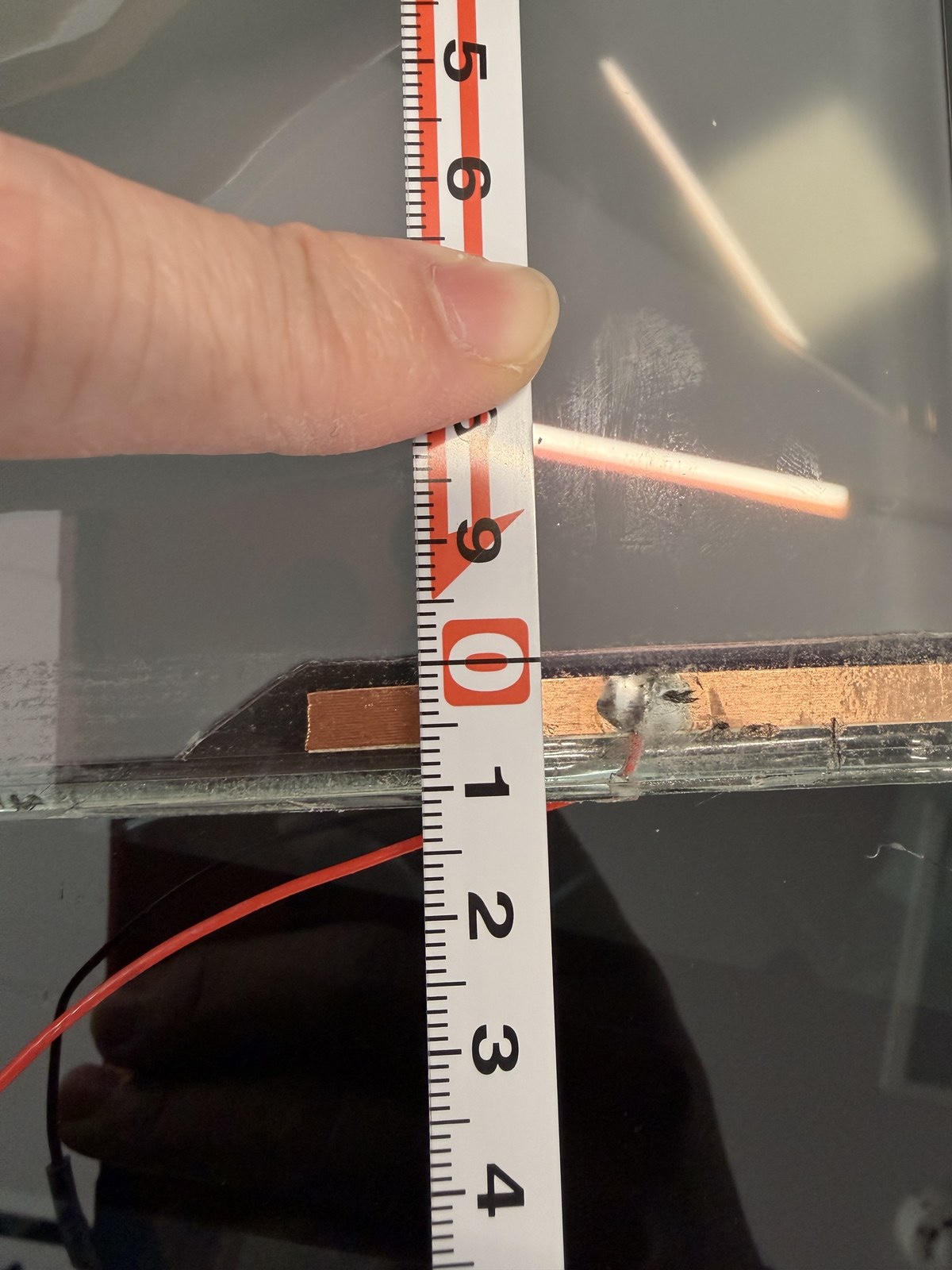
- 電極要隱藏在窗框溝槽裡 — 玻璃上下緣(或側緣)有 6 mm 寬電極區,必須藏入窗框溝槽,否則暴露在外不美觀。
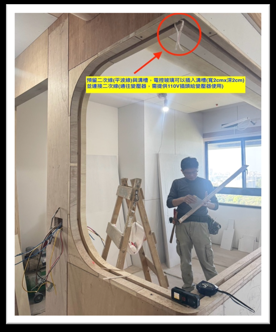
- 窗框要預留出線孔給二次線 — 二次線(不帶電的平波線)從電極連出,須穿過窗框上的開孔走到變壓器;現場需有 110V 插座供變壓器使用。
- 電極はサッシの溝内に隠す —— ガラスの上下端(または側端)には幅 6 mm の電極部があり、サッシの溝に納める必要があります。露出したままでは意匠を損ないます。
- サッシに二次側配線用の取出し孔を設ける —— 二次側配線(通電していないフラットケーブル)は電極から引き出され、サッシに設けた開口を通してトランスまで配線します。現場にはトランス用の 100V コンセントが必要です。
- Conceal the electrode inside the frame groove — there is a 6 mm-wide electrode strip along the top/bottom (or side) edges; this must be hidden inside the frame groove, otherwise it will be visible.
- Reserve an exit hole for the secondary wiring — the secondary wire (a non-powered ribbon cable) runs from the electrode through a hole in the frame and out to the transformer. A 110V outlet for the transformer is also required on site.
窗框立面 — 出線孔要開幾處(依做法決定)
サッシ立面 — 配線取出し孔は何箇所必要か(納まりによって決まります)
Frame Elevation — How Many Wire Exits (Depends on the Layout)
出線孔不是一律上下各開一處。開幾處由「玻璃有沒有落地、有多高」決定:
取出し孔は「上下に必ず 1 箇所ずつ」ではありません。箇所数は「ガラスが床まで達しているか、どれだけの高さか」で決まります:
Exit holes are not always one at the top and one at the bottom. How many you need depends on whether the glass runs to the floor, and how tall it is:
- 半牆做法(玻璃未落地,下方是矮牆或櫃體)—— 只要上緣一處出線即可,不必在下方另外開孔。
- 落地做法(從天花直接落地,高度超過 190 cm)且為玻璃拼玻璃的分割 —— 上、下各需一處出線。只做上緣單邊供電,下半段會不夠穿透。
- 腰壁納まり(ガラスが床まで達さず、下部が腰壁または家具)—— 上端 1 箇所の取出しで足ります。下部に別途開口を設ける必要はありません。
- 床まで達する納まり(天井から床まで、高さが 190 cm を超える)で、かつガラス突付けの割付の場合 —— 上下それぞれ 1 箇所の取出しが必要です。上端片側のみの給電では、下半分の透過が不足します。
- Half-height layout (glass does not reach the floor; a low wall or cabinet below) — a single exit at the top is enough; no second hole is needed at the bottom.
- Floor-to-ceiling layout (over 190 cm tall) with a glass-to-glass division — one exit at the top and one at the bottom. Feeding from the top edge alone leaves the lower half not clear enough when switched on.
現場有窗框時 — 二次側走框外、一次側收在維修孔
既存サッシがある場合 — 二次側はサッシ外、一次側は点検口に納める
When There Is a Frame On Site — Secondary Outside the Frame, Primary in the Access Panel
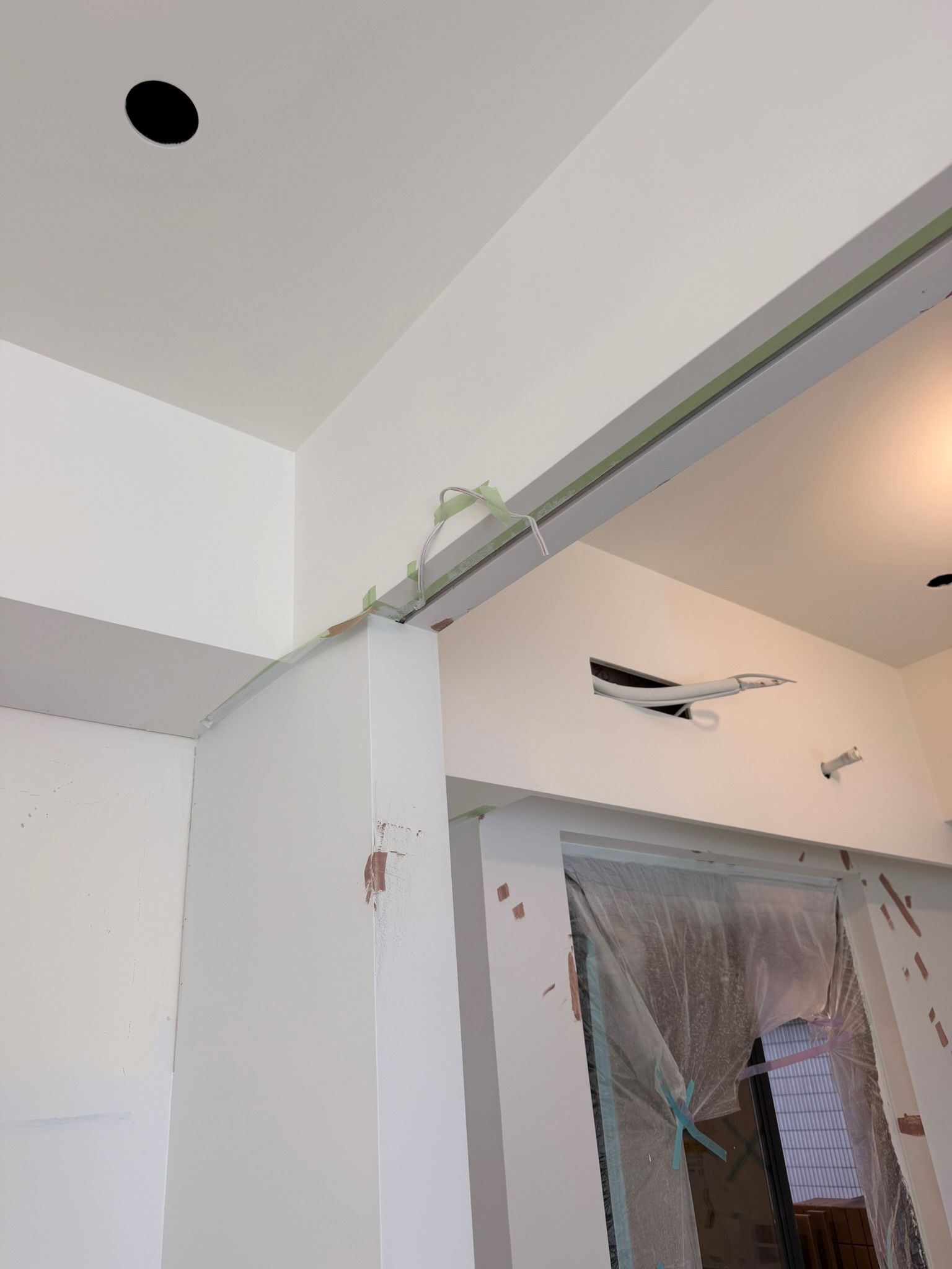
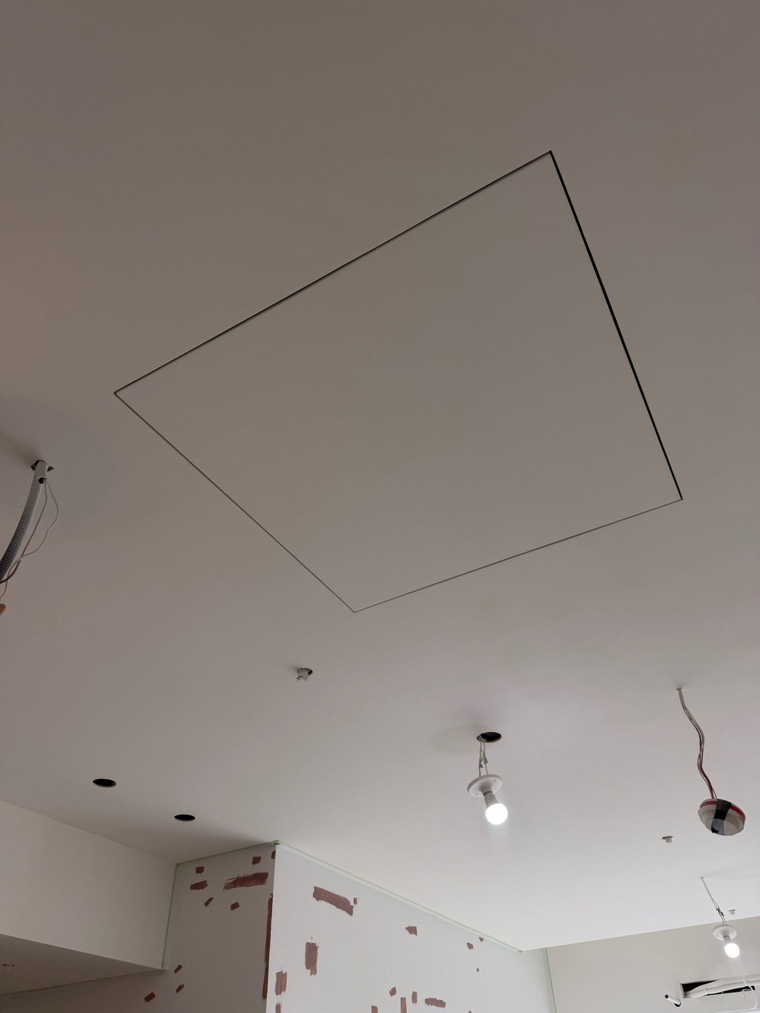
現場若已有金屬窗框/框料,二次側(不帶電的平波線)要拉到窗框外面再走到變壓器,不要試圖硬塞在框內;一次側(110V 插座與變壓器)則可以收在天花的維修孔內,維修時掀開即可接觸,平常完全看不到。
現場に既に金属サッシ/フレーム材がある場合、二次側(通電していないフラットケーブル)はサッシの外側に引き出してからトランスまで配線してください。フレーム内に無理に押し込まないでください。一次側(100V コンセントとトランス)は天井の点検口内に納めることができ、メンテナンス時は蓋を開ければアクセスでき、普段は完全に見えません。
Where a metal frame already exists on site, bring the secondary-side (non-powered ribbon) wire out to the outside of the frame and run it to the transformer — do not force it inside the frame profile. The primary side (110V outlet and transformer) can be housed in a ceiling access panel: reachable for maintenance, invisible in daily use.
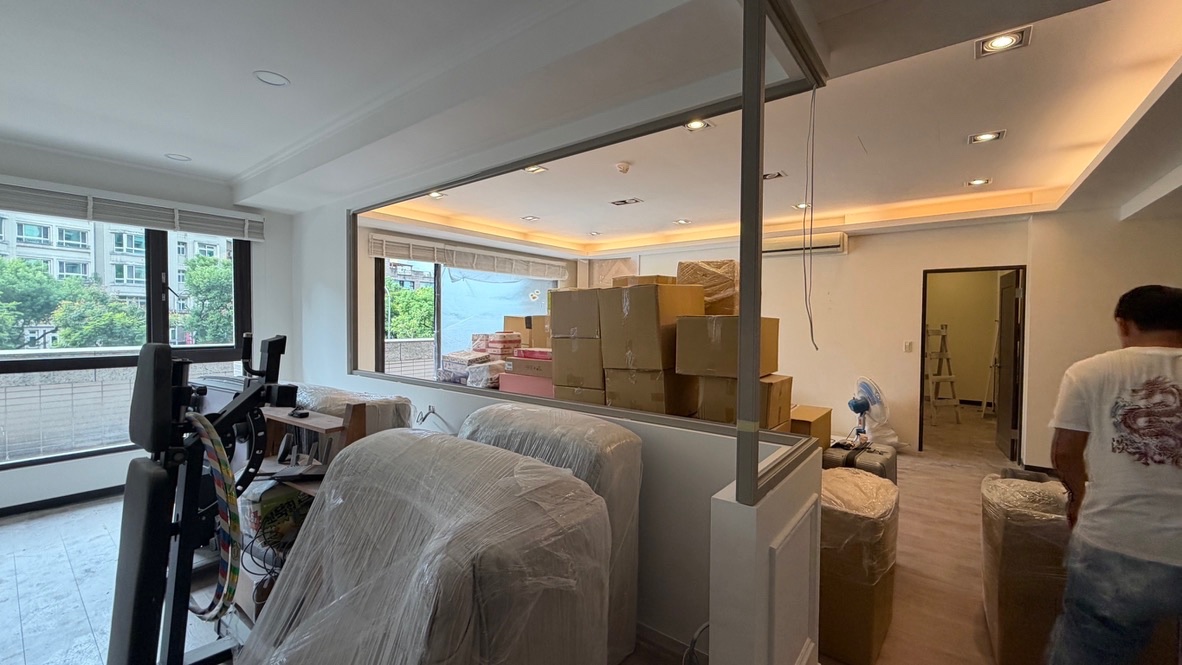
兩種電控玻璃結構(橫切面)
2 種類の調光ガラス構成(断面)
Two Glass Structures (Cross-Section)
電控玻璃有兩種做法,液晶膜的位置不同,但施工邏輯(電極藏溝槽 + 二次線拉出)相同。
調光ガラスには 2 つの構成があります。調光フィルムの位置は異なりますが、施工の考え方(電極を溝に隠す+二次側配線を引き出す)は同じです。
There are two construction methods. The film sits in a different place, but the installation logic — concealed electrode + secondary wiring — is the same.
窗框溝槽與電極/二次線(剖面概念)
サッシの溝と電極/二次側配線(断面の考え方)
Frame Groove + Electrode + Secondary Wire (Section)
無論膠合式或直貼式,玻璃上緣(或下緣)的電極都必須藏入窗框溝槽,二次線從電極延伸後穿過窗框出線孔走到變壓器。
合わせ式・直貼り式のいずれの場合も、ガラス上端(または下端)の電極は必ずサッシの溝内に納めてください。二次側配線は電極から延び、サッシの取出し孔を通してトランスまで配線します。
Whether laminated or self-adhesive, the electrode along the top (or bottom) edge of the glass must be hidden inside the frame groove. The secondary wire then runs from the electrode through the frame's exit hole and out to the transformer.
- 天花板內部空間放置變壓器(STARTEK 110×46×179 mm 或明基 AWS100 69×242×44 mm)
- 110V 插座於天花板內供變壓器使用
- 窗框上緣出線孔讓二次線從電極鑽入天花板
- トランスを設置する天井内部のスペース(STARTEK 110×46×179 mm または BenQ AWS100 69×242×44 mm)
- トランス用の100V コンセント(天井内)
- 二次側配線を電極から天井内へ引き込むための、サッシ上端の取出し孔
- Ceiling-cavity space for the transformer (STARTEK 110×46×179 mm or BenQ AWS100 69×242×44 mm)
- 110V outlet inside the ceiling cavity to feed the transformer
- Wire exit hole at the top of the frame for the secondary wire to route into the ceiling
現場參考照片
現場参考写真
Site Reference Photos


- 窗框溝槽 W 15 mm × D 20 mm(容納玻璃 + 電極 + 墊片 + 矽利康)
- 窗框預留出線孔給二次線 —— 半牆做法上緣一處即可;落地且高度超過 190 cm 的玻對玻做法,上、下各一處(見本章「窗框立面」)
- 玻璃兩側以中性 Silicone 矽利康封邊(指定品牌:Dow Corning N2 / Toshiba 381)
- 現場需有 110V 插座供變壓器使用
- サッシ溝 W 15 mm × D 20 mm(ガラス + 電極 + セッティングブロック + シーリング材を納める寸法)
- サッシに二次側配線用の取出し孔を確保 —— 腰壁納まりは上端 1 箇所で足ります/床まで達し高さ 190 cm を超えるガラス突付け納まりでは上下 1 箇所ずつ(本章「サッシ立面」参照)
- ガラスの両側は中性シリコーン系シーリング材で止水(指定ブランド:Dow Corning N2 / Toshiba 381)
- 現場にトランス用の 100V コンセントが必要
- Frame groove W 15 mm × D 20 mm (accommodates glass + electrode + setting block + silicone)
- Wire exit hole(s) in the frame for the secondary wiring — one at the top for a half-height layout; one at the top and one at the bottom for floor-to-ceiling glass-to-glass over 190 cm (see "Frame Elevation" in this section)
- Seal both glass edges with neutral silicone (specified brands: Dow Corning N2 / Toshiba 381)
- A 110V outlet on site is required for the transformer
技術細節(給工班 / 細部圖面)
技術詳細(施工業者・詳細図向け)
Technical Detail (for installers / shop drawings)
| 窗框溝槽尺寸 | W 15 mm × D 20 mm(容納電極 + 玻璃 + 墊片 + 矽利康) 單片玻璃過大、變形量較大時,或圓弧彎烤膠合式電控玻璃,建議溝槽加大到 W 30 mm × D 30 mm。 |
|---|---|
| 窗框出線孔 | 半牆做法:頂部一處;落地且高度超過 190 cm 的玻對玻做法:頂部 + 底部各一處。實際位置依電極設計(單邊 / 雙邊)決定 |
| 玻璃 | 5+5 mm 膠合式電控玻璃 |
| 玻璃下方墊片 | 玻璃與窗框溝槽底間以墊片支撐 |
| 玻璃兩側固定 | 中性矽利康(Silicone) |
| 電極區寬度 | 6 mm(於玻璃上下緣或側緣) |
| 二次線 | 不帶電平波線,從電極延伸經窗框出線孔走到變壓器 |
| 變壓器至玻璃 A 點 | 使用 1.6 mm 白扁線連接 |
| サッシ溝の寸法 | W 15 mm × D 20 mm(電極 + ガラス + セッティングブロック + シーリング材を納める) 1 枚のガラスが大きく変形量が大きい場合、または曲面(曲げ)合わせ式の調光ガラスでは、溝を W 30 mm × D 30 mm まで拡大することをお勧めします。 |
|---|---|
| サッシの取出し孔 | 腰壁納まり:上部 1 箇所/床まで達し高さ 190 cm を超えるガラス突付け納まり:上部 + 下部 各 1 箇所。実際の位置は電極設計(片側 / 両側)によって決まります |
| ガラス | 5+5 mm 合わせ式調光ガラス |
| ガラス下部のセッティングブロック | ガラスとサッシ溝底の間をセッティングブロックで支持します |
| ガラス両側の固定 | 中性シリコーン系シーリング材 |
| 電極部の幅 | 6 mm(ガラスの上下端または側端) |
| 二次側配線 | 通電していないフラットケーブル。電極から延び、サッシの取出し孔を通してトランスへ配線します |
| トランスからガラス A 点まで | 1.6 mm 白色平型ケーブルで接続します |
| Frame Groove | W 15 mm × D 20 mm (accommodates electrode + glass + setting block + silicone) For oversized panels with greater deformation, or curved tempered laminated smart glass, increase the groove to W 30 mm × D 30 mm. |
|---|---|
| Wire Exit Holes | Half-height layout: one at the top. Floor-to-ceiling glass-to-glass over 190 cm: one at the top and one at the bottom. Exact positions follow the electrode layout (single- or double-edge) |
| Glass | 5+5 mm laminated smart glass |
| Setting Block | Supports the glass against the bottom of the frame groove |
| Side Fixing | Neutral silicone |
| Electrode Strip Width | 6 mm (along top/bottom or side edges of the glass) |
| Secondary Wire | Non-powered ribbon cable; runs from electrode through the frame exit hole to the transformer |
| Transformer → Glass Point A | Connect with 1.6 mm white flat cable |
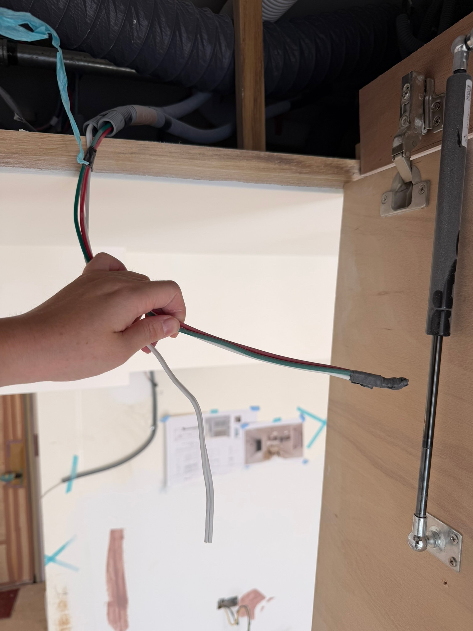
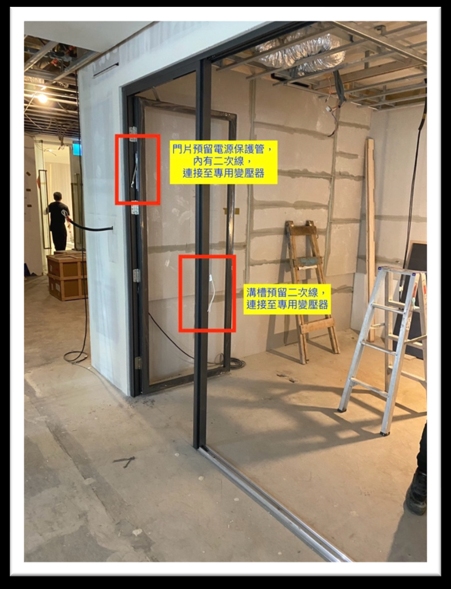
現地溝槽與預留二次線(平波線,不帶電)
現場の溝と先行配線した二次側ケーブル(フラットケーブル、非通電)
Site Groove & Pre-Routed Secondary Wire (non-powered ribbon)
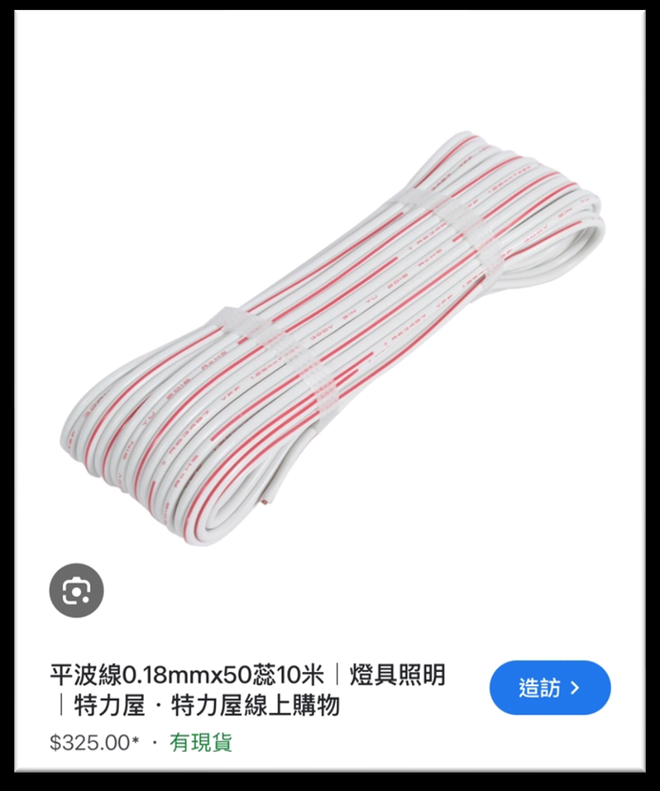
- 在需安裝電控玻璃的位置預留不帶電的二次線(平波線 0.18 mm × 50 蕊,10 米規格)。
- 此二次線將連接到明星電控配置之專用電控玻璃變壓器(AC 110V → AC 60/48V),現場需有 110V 插座供此變壓器使用,並需有放置變壓器的空間(變壓器尺寸請參考第 10 章)。
- 若是已經有玻璃需要後貼電控液晶調光膜,也需要預留電源插座以及二次線。並且要注意收邊條材質(要收納電線以及電極,寬約 10–12 mm),需與現場介面顏色相近,避免突兀。
- 調光ガラスを施工する位置に、非通電の二次側配線(フラットケーブル 0.18 mm × 50 芯、10 m 規格)を先行配線してください。
- この二次側配線は、STARTEK が指定する調光ガラス専用トランス(AC 110V → AC 60/48V)に接続します。現場にはこのトランス用の 100V コンセントと、トランスを設置するスペースが必要です(トランスの寸法は第 10 章をご参照ください)。
- 既存のガラスに調光フィルムを後貼りする場合も、電源コンセントと二次側配線の先行手配が必要です。あわせて見切り材の材質にもご注意ください(配線と電極を納めるため幅は約 10〜12 mm)。現場の見切りの色に近いものを選び、違和感が出ないようにしてください。
- At each smart-glass location, pre-route a non-powered secondary wire (0.18 mm × 50-core ribbon cable, 10 m length).
- This wire connects to STARTEK's dedicated transformer (AC 110V → AC 60/48V). The site must provide a 110V outlet and space for the transformer (see Section 10 for dimensions).
- For retrofitting film onto existing glass, also reserve a power outlet and secondary wire. Match the edge trim (~10–12 mm wide, covering both wire and electrode) to the surrounding surface colour to avoid a visual clash.
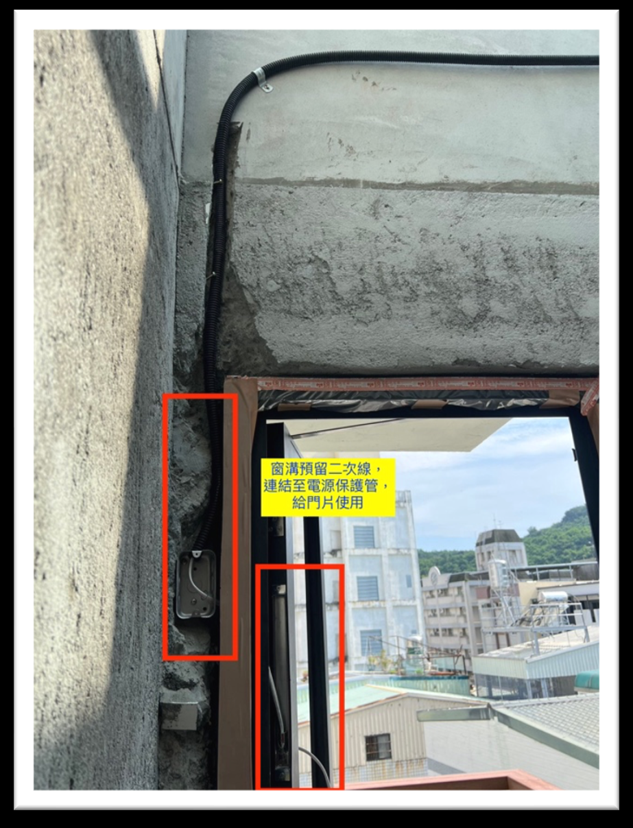
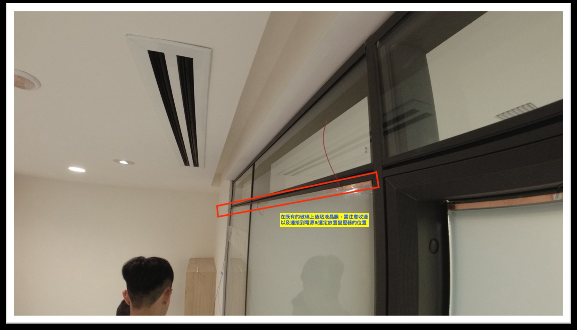
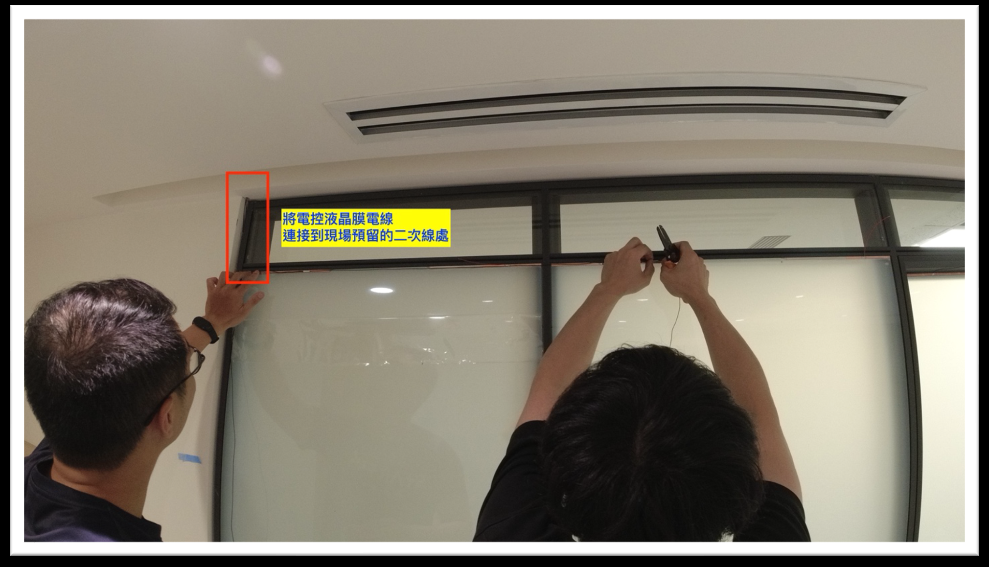
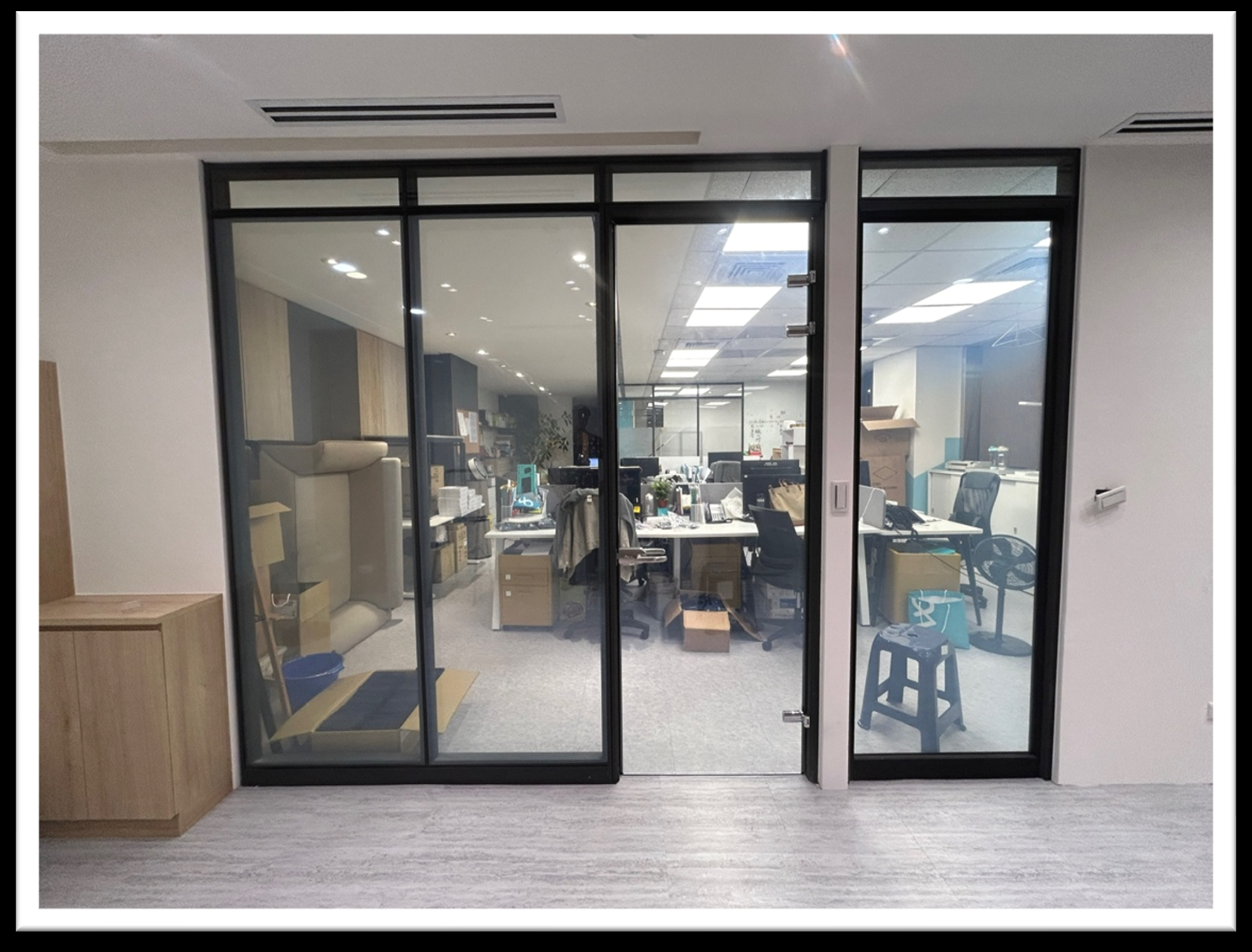
既有玻璃後貼液晶膜 — 事前必談的四件事
既存ガラスへの調光フィルム後貼り — 事前に必ず確認すべき 4 点
Retrofit Film on Existing Glass — Four Things to Agree Up Front
既有玻璃直接後貼(SQUID 直貼式)可以沿用現場既有的玻璃,玻璃材料的預算會比重新製作膠合式(OYSTER)低一些。但它不是「比較便宜」的萬用解——工法本身有三項限制,明星電控並不鼓勵客戶一律採用直貼式,請先確認現場條件真的適合,再談價格。
既存ガラスへの直接後貼り(SQUID 直貼り式)は、現場にある既存ガラスをそのまま活かせるため、ガラス材料の予算は合わせ式(OYSTER)を新規製作する場合よりいくらか抑えられます。ただし「安く済む万能な選択肢」ではありません —— 工法自体に 3 つの制約があり、STARTEK はすべてのお客様に直貼り式をお勧めしているわけではありません。現場条件が本当に適しているかをご確認いただいたうえで、価格のお話に進んでください。
Retrofitting film onto existing glass (SQUID self-adhesive) reuses the glass already on site, so the glass material budget is somewhat lower than making new laminated (OYSTER) glass. It is not, however, a cheaper universal answer — the method itself carries three limitations, and STARTEK does not recommend defaulting every project to self-adhesive. Confirm that the site genuinely suits the method before discussing price.
- 施工時間較長 — 直貼採靜電乾貼工法,現場逐片貼膜;膠合式是工廠完成、現場只做玻璃安裝,因此直貼的現場作業時間明顯較長。
- 工資成本較高 — 施工時間長,人工成本就跟著上去,玻璃材料省下來的部分會有一些回到工資上。現場也必須配合,給得出足夠的施作時間。
- 現場環境限制 — 貼膜必須在非常乾淨、沒有粉塵的環境下進行。若現場粗工、木作、油漆未完成或粉塵未清,就不具備貼膜條件,須先安排清潔並排定合適的進場順序。
- 施工時間が長くなります —— 直貼りは静電気による乾式貼付工法で、現場で 1 枚ずつフィルムを貼ります。合わせ式は工場で完成させ現場ではガラスの取付のみのため、直貼りは現場作業時間が明らかに長くなります。
- 施工費が高くなります —— 施工時間が長くなれば人件費も上がるため、ガラス材料で抑えた分の一部は施工費に戻ります。現場側にも、十分な施工時間を確保していただく必要があります。
- 現場環境の制約 —— フィルムの貼付は非常に清浄で粉塵のない環境で行う必要があります。躯体工事・木工事・塗装が未完了であったり粉塵が残っていたりする現場では、貼付の条件を満たしません。事前に清掃を手配し、適切な入場順序を組んでください。
- Longer installation time — self-adhesive uses a dry, electrostatic application done panel by panel on site, whereas laminated glass is finished at the factory and merely installed on site. On-site working time is therefore noticeably longer.
- Higher labour cost — longer installation means higher labour cost; part of what is saved on glass material comes back as labour. The site must also be able to allow enough working time.
- Strict site-condition requirement — film must be applied in a very clean, dust-free environment. If rough works, carpentry or painting are unfinished or dust has not been cleared, the site is not ready for film application; cleaning and a suitable sequencing of trades must be arranged first.
確認直貼式適合之後,還有四件事和「重新製作電控玻璃」本質不同:電極沒有框可以藏、膜有幅寬上限、現場電器位置無法更動、清潔方式受限。這四件事客戶通常不知道,必須在報價與簽約前講清楚,避免完工後才發生認知落差。
直貼り式が適していると確認できた後も、「調光ガラスを新規に製作する」場合とは本質的に異なる 4 点があります:電極を隠すフレームがない、フィルムに幅の上限がある、現場の電気設備の位置を変更できない、清掃方法に制限がある。この 4 点はお客様がご存じないことが多いため、お見積り・ご契約の前に必ずご説明ください。完工後の認識の食い違いを防ぐためです。
Once self-adhesive is confirmed as suitable, four further things differ fundamentally from newly made smart glass: there is no frame to conceal the electrode, the film has a maximum roll width, existing electrical positions cannot be moved, and cleaning is restricted. Customers are usually unaware of all four — they must be agreed before quotation and contract to avoid a gap in expectations after completion.
① 電極一定會外露 — 收邊是必要工項,不是選配
① 電極は必ず露出します — 見切り処理は必須工事であり、オプションではありません
① The electrode will be exposed — edge trim is required, not optional
② 幅寬限制 — 大尺寸玻璃務必先確認幅寬
② 幅の制限 — 大判ガラスでは必ず事前に幅を確認してください
② Roll-width limit — confirm the width before committing to large panels
- 現場丈量時逐片取得實際寬高,不要只量整面牆。
- 報價前先與 STARTEK 確認該尺寸是否落在幅寬內。
- 若確定必須拼接,事先與客戶確認拼接縫的位置(盡量落在玻璃分割線、櫃體或視覺不明顯處),並取得書面同意後再施作。
- 現場調査では1 枚ごとに実寸法(幅・高さ)を採寸してください。壁面全体だけを測るのでは不十分です。
- お見積り前に、その寸法がフィルム幅に収まるかを STARTEK にご確認ください。
- 継ぎ足しが避けられない場合は、継ぎ目の位置を事前にお客様とご確認ください(ガラスの割付線、家具の陰、視覚的に目立たない位置に寄せます)。書面でのご同意をいただいてから施工してください。
- Measure each panel individually on site — not just the overall wall.
- Confirm with STARTEK whether the size falls within the roll width before quoting.
- If a joint is unavoidable, agree the seam position with the customer in advance (align it with a panel division, cabinetry, or a visually discreet line) and obtain written approval before proceeding.
③ 貼膜前先確認電器與電極位置
③ フィルム貼付前に、電気設備と電極の位置を確認してください
③ Confirm electrical and electrode positions before applying the film
後貼案場的電源、開關、插座、二次線走線都必須在現場既有條件下解決,能動的空間有限。STARTEK 場勘後會出具「案場勘查設計建議報告書」,在現場照片上標示每一片玻璃的電極位置與二次線走線。貼膜前務必依此報告與客戶/設計師逐片確認 — 電極決定收邊條落在哪一邊,二次線決定要在哪裡預留出線與插座;膜一旦貼上去就無法變更。
後貼り現場では、電源・スイッチ・コンセント・二次側配線の経路をすべて現場の既存条件の中で解決する必要があり、動かせる余地は限られます。STARTEK は現場調査後に「現場調査・設計提案報告書」を発行し、現場写真の上に 1 枚ごとの電極位置と二次側配線の経路を明示します。フィルム貼付前に、必ずこの報告書に基づいてお客様/設計者と 1 枚ずつご確認ください —— 電極が見切り材をどちら側に納めるかを決め、二次側配線が取出しとコンセントをどこに確保するかを決めます。フィルムは一度貼ると変更できません。
On a retrofit, the power supply, switches, outlets and secondary-wire routing all have to work within existing site conditions, leaving little room to adjust. After a site survey STARTEK issues a Site Survey & Design Recommendation Report, which marks the electrode position and wire routing of every panel on the site photo. Walk through this report panel by panel with the customer and designer before any film is applied — the electrode decides which edge carries the trim, and the wiring decides where the exit point and outlet must be reserved. Once the film is on, none of this can be changed.

④ 清潔保養(直貼式限定)
④ 清掃・お手入れ(直貼り式限定)
④ Cleaning & care (self-adhesive only)
- 不可直接在玻璃表面噴灑水劑、水氣或任何清潔保養品。
- 需要擦拭時,將中性清潔劑(例如穩潔)噴在清潔布上,再進行局部擦拭即可。
- 絕對不能整片噴灑任何清潔劑或水劑 — 液體會沿膜的邊緣、電極區或拼接縫滲入,造成液晶膜後續出現瑕疵與損壞。
- ガラス表面に、水溶液・水分・各種の洗浄/お手入れ用品を直接スプレーしないでください。
- 拭き取りが必要な場合は、中性洗剤(ガラスクリーナーなど)を清掃用の布に吹き付けてから、部分的に拭き取ってください。
- 洗浄剤・水溶液を面全体にスプレーすることは絶対に避けてください —— 液体がフィルムの端部、電極部、継ぎ目から浸入し、後に調光フィルムの不具合や損傷の原因となります。
- Do not spray water, moisture, or any cleaning or care product directly onto the glass surface.
- To clean, spray a neutral cleaner onto the cloth and wipe the affected spot only.
- Never spray any cleaner or liquid across the whole panel — liquid wicks in along the film edge, the electrode strip, or a film joint and causes defects and damage to the film over time.
電控玻璃橫拉門 / 滑門 安裝施作
調光ガラス 引戸 / スライドドアの施工
Sliding Door Installation
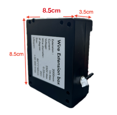
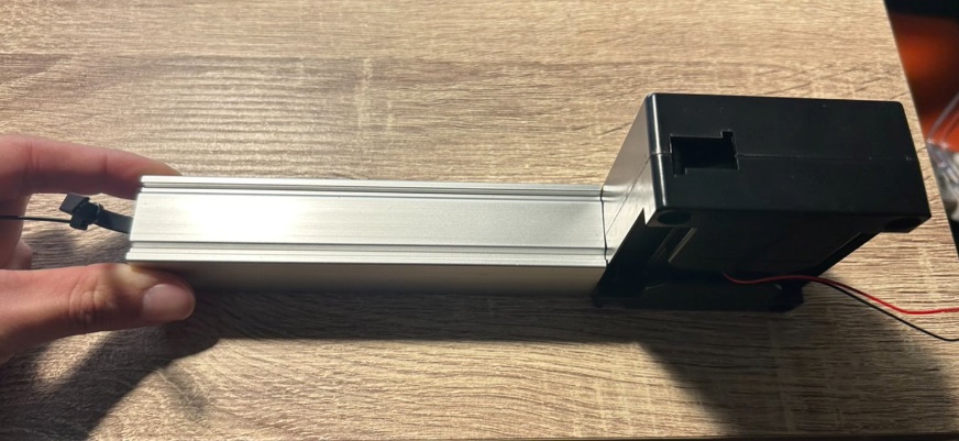
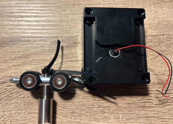
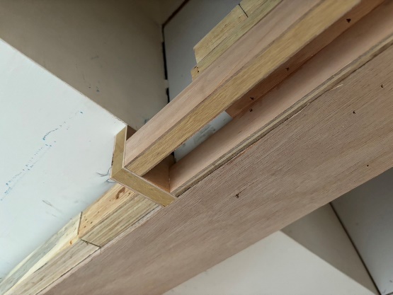
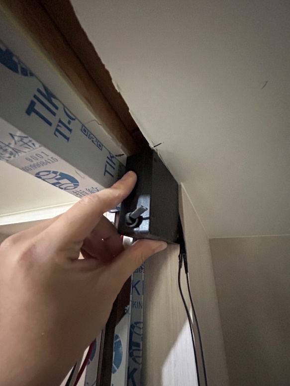
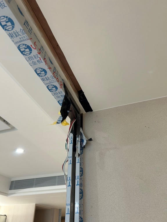
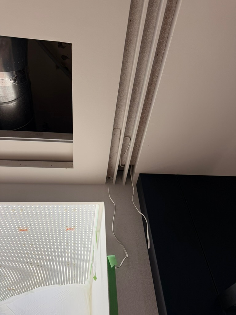
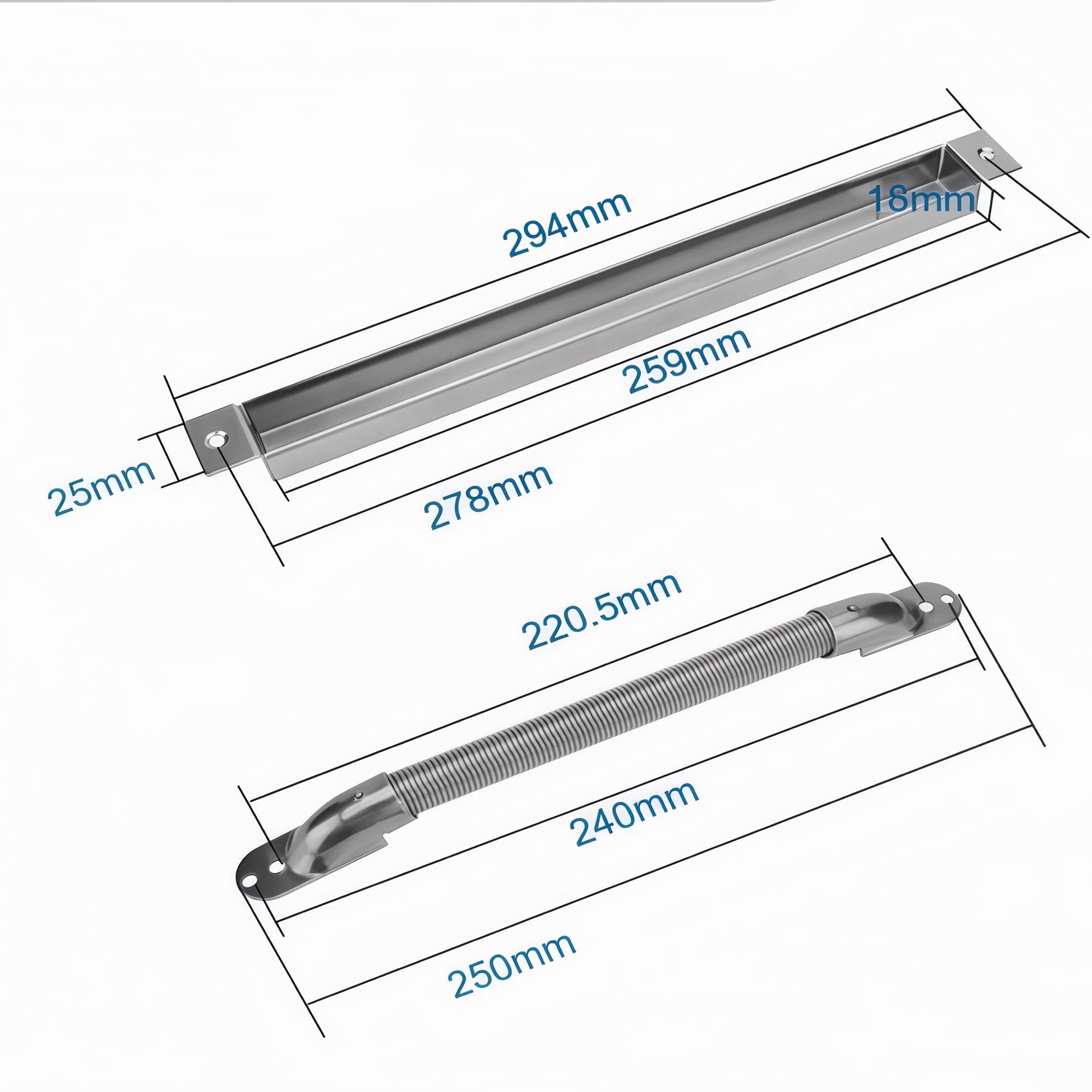
- 於軌道後方預留「伸縮電線盒」放置空間。線盒本體尺寸為 8.5 cm × 8.5 cm × 3.5 cm,但開孔寬度請做 9.5 cm —— 盒體前方還帶著電線,若直接照本體 8.5 cm 開孔,現場會塞不進去。
- 伸縮電線處須開維修口,以便後續接線施工與維修更換。
- 伸縮線盒下緣需與軌道切齊,不能有高低落差。
- 伸縮電線可拉出長度為 260 cm(2.6 m),規劃維修口與電源位置的距離時可作為參考。
- レール後方に「伸縮電線ボックス」の設置スペースを確保してください。ボックス本体の寸法は 8.5 cm × 8.5 cm × 3.5 cm ですが、開口幅は 9.5 cm としてください —— ボックス前面にも配線があるため、本体寸法どおり 8.5 cm で開口すると現場で納まりません。
- 伸縮電線の位置には点検口を設け、後の結線作業やメンテナンス・交換に対応できるようにしてください。
- 伸縮電線ボックスの下端はレールと面一とし、段差が生じないようにしてください。
- 伸縮電線の引出し可能長さは 260 cm(2.6 m)です。点検口と電源位置の距離を計画する際の目安としてください。
- Reserve space behind the track for the "retractable wire box". The box body measures 8.5 cm × 8.5 cm × 3.5 cm, but cut the opening 9.5 cm wide — the lead-out wiring sits in front of the box body, so an opening cut to the 8.5 cm body dimension is too tight to fit on site.
- Provide an access panel at the retractable wire box for wiring work and future maintenance.
- The bottom edge of the wire box must align flush with the track — no level difference is allowed.
- The retractable lead extends to 260 cm (2.6 m) — use this when planning the distance between the access panel and the power position.
橫拉門鋁料細部圖(設計師參考)
引戸アルミ材ディテール図(設計者参考用)
Sliding Door Aluminum Profiles (Designer Reference)
懸吊橫拉門的立框、上下框與懸吊軌道細部圖如下,供設計師繪圖與納入施工圖說使用。立框兩款:LD(正面 22.5 mm,線條細緻)與 LS(正面 33 mm,五金包容度最高);上下框與懸吊軌道為共用料件。
吊り引戸の方立、上下枠、吊りレールのディテール図を以下に示します。設計時の作図および施工図への反映にご利用ください。方立は 2 種類:LD(見付け 22.5 mm、繊細な線)と LS(見付け 33 mm、金物の対応幅が最も広い)。上下枠と吊りレールは共通部材です。
Detail drawings of the posts, top/bottom rails and hanging tracks of the top-hung sliding door system, for designers to reference in drawings and shop documents. Two post profiles are available: LD (22.5 mm face, refined line) and LS (33 mm face, highest hardware capacity). The top/bottom rails and hanging tracks are shared between both.


- 鋁料料長限制 3000 mm 以內。
- 適用 5–11 mm 玻璃/板材;吊軌承重最高 100 kg。
- 懸吊軌道鎖入上方結構面,建議搭配木作軌道盒收整。
- 無下軌設計、不破壞地面;多片式門片請改用特規軌道。
- アルミ材の材長制限は 3000 mm 以内です。
- 適用板厚は 5〜11 mm のガラス/板材、吊りレールの耐荷重は最大 100 kg です。
- 吊りレールは上部の構造面に固定します。木工事によるレールボックスとの併用を推奨します。
- 下レールなしの設計で床を傷めません。多連戸の場合は特注レールをご使用ください。
- Profile stock length is limited to 3000 mm.
- Accepts 5–11 mm glass or panels; hanging track load capacity up to 100 kg.
- The hanging track fixes into the structure above — a carpentry track box is recommended to conceal it.
- No floor track — the floor stays untouched; use the wide track for multi-panel doors.
鋁框烤漆色樣 — 常用烤漆色如下,可依設計需求指定:
アルミ枠 焼付塗装カラーサンプル — よくお選びいただく色は以下のとおりです。設計のご要望に応じてご指定ください:
Frame Coating Colours — commonly specified coating colours:




腰帶式(中段)施工注意事項
腰帯(中段)施工の注意事項
Mid-Band Application — Installation Notes
常見情境:玻璃整片到底(單片大玻璃),液晶膜只貼中段橫向腰帶區,上下保留透明玻璃。這種做法視覺輕盈,但施工要特別處理三件事:
よくあるケース:ガラスは床まで 1 枚(大判ガラス)とし、調光フィルムは中段の横帯部分のみに貼り、上下は透明ガラスのまま残す納まりです。視覚的に軽やかですが、施工上は次の 3 点に特に注意が必要です:
A common scenario: full-height glass (single large panel) with film applied only to a horizontal mid-band, leaving the top and bottom transparent. The result looks light and elegant, but three things need attention on site:

- 液晶膜邊緣外露 — 膜的橫截面(厚度方向約 0.27–0.55 mm)會在腰帶上下緣露出,視覺上看得到膜邊。需以收邊條覆蓋以保持整體美觀。
- 電極區(銀漿 / 銅網)必須遮蔽 — 收邊條規格與後貼調光膜同(寬約 10–12 mm),須與現場介面(玻璃框、牆面)顏色相近,避免突兀。
- 二次線出線規劃 — 因玻璃整片到底,膜只在中段,二次線從電極上緣出線後沒有自然路徑可藏。需事先與設計師確認出線方向(往天花、往側框、或藏入特殊收邊條),並在現場預留對應通道。
- 調光フィルムの端部が露出します —— フィルムの断面(厚み方向 約 0.27〜0.55 mm)が腰帯の上下端に露出し、フィルムの縁が見えます。全体の意匠を保つため、見切り材で覆う必要があります。
- 電極部(銀ペースト / 銅メッシュ)は必ず隠してください —— 見切り材の仕様は後貼り調光フィルムと同じ(幅 約 10〜12 mm)で、現場の見切り(ガラス枠・壁面)と近い色を選び、違和感が出ないようにします。
- 二次側配線の取出し計画 —— ガラスが床まで 1 枚で、フィルムが中段のみのため、電極上端から引き出した二次側配線を自然に隠す経路がありません。取出し方向(天井方向、側枠方向、または専用の見切り材内に隠す)を設計者と事前にご確認いただき、現場に対応する経路をあらかじめ確保してください。
- Exposed film edge — the cross-section of the film (0.27–0.55 mm) shows at the top and bottom of the mid-band and is visually noticeable. Cover with edge trim to keep the appearance clean.
- Electrode strip (silver paste / copper mesh) must be concealed — same trim spec as retrofit film (~10–12 mm wide); match the surrounding colour (frame, wall) to avoid a visual clash.
- Plan the secondary wire exit — because the glass runs full-height with film only at the mid-band, the wire has no natural path to hide after exiting the top of the electrode. Confirm the exit direction with the designer in advance (ceiling, side frame, or hidden trim) and reserve the corresponding channel on site.
電梯尺寸確認(進場前必確認)
エレベーター寸法の確認(搬入前の必須確認事項)
Elevator Size Check (Confirm Before Delivery)
大尺寸玻璃(尤其 STARTEK 1 系列最大可至 4,500 × 2,000 mm,明基系列至 1,500 × 3,000 mm)進場時,能否搬入是首要問題。客戶在規劃玻璃分割尺寸時,務必同時確認以下兩組電梯尺寸:
大判ガラス(特に STARTEK 1 シリーズは最大 4,500 × 2,000 mm、明基シリーズは 1,500 × 3,000 mm まで対応)を搬入する際は、そもそも搬入できるかが最優先の問題となります。ガラスの割付寸法をご検討いただく際は、必ず以下 2 組のエレベーター寸法もあわせてご確認ください:
For large panels (STARTEK 1 Series up to 4,500 × 2,000 mm, BenQ Series up to 1,500 × 3,000 mm), the first question is whether the glass can physically be brought in. When planning panel divisions, customers must confirm both sets of elevator dimensions:
- 電梯開門尺寸(藍色標示)— 寬 W、高 H:決定玻璃能否「水平」搬入電梯。
- 電梯車廂尺寸(紅色標示)— 寬 W、深 D、高 H:玻璃進入電梯後是否能直立、斜放或平放,受車廂內部三軸限制。
- エレベーターの出入口寸法(青色表示)— 幅 W、高さ H:ガラスを「水平に」エレベーターへ搬入できるかを左右します。
- かご内寸法(赤色表示)— 幅 W、奥行 D、高さ H:エレベーターに入れた後、ガラスを立てる・斜めにする・寝かせることができるかは、かご内部の 3 方向の寸法に制約されます。
- Elevator door opening (blue) — Width W, Height H: determines whether the glass can be carried horizontally into the car.
- Elevator car interior (red) — Width W, Depth D, Height H: determines whether, once inside, the glass can stand upright, lean, or lie flat — constrained by all three axes.
有框開關門 安裝施作
框付き開き戸の施工
Framed Swing Door Installation
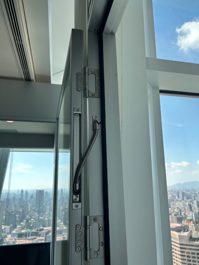
- 適用於「單向開」且五金為「蝴蝶鉸鍊」的做法。
- 於門框及門斗框預埋「電源保護管」。
- 電線從天花板落至門斗框內,經「電源保護管」與進入門框與電控玻璃相接。
- 「片開き」で金物が「バタフライヒンジ」の納まりに適用します。
- 戸枠および方立枠に「電源保護管」を先行埋設します。
- 配線は天井から方立枠内へ落とし、「電源保護管」を経由して戸枠に入り、調光ガラスへ接続します。
- Applies to single-direction swing doors with butterfly-hinge hardware.
- Pre-embed a "power conduit" inside the door frame and head frame.
- Wires drop from the ceiling into the head frame, run through the conduit, and connect to the glass inside the door frame.
矽利康選用與填縫規範
シーリング材の選定と目地施工規範
Silicone Selection & Joint Sealing
矽利康不是收尾的裝飾,而是電控玻璃的最後一道保護。它同時決定兩件事:① 液晶膜會不會被膠體釋放的化學物質腐蝕;② 水氣會不會從邊緣滲進膜層。膜層一旦受損無法局部修復,只能整片更換 — 所以「選哪支膠」與「留多少縫」必須在設計階段就決定,不是等到現場收尾才處理的事。
シーリング材は仕上げの装飾ではなく、調光ガラスにとって最後の防護層です。次の 2 点を同時に左右します:① シーリング材から放出される化学物質によって調光フィルムが侵されないか、② 水分が端部からフィルム層へ浸入しないか。フィルム層は一度損傷すると部分補修ができず、1 枚まるごとの交換となります —— したがって「どのシーリング材を使うか」「どれだけ目地を取るか」は設計段階で決めるべき事項であり、現場の仕上げ時に考えることではありません。
Silicone is not a finishing touch — it is the last line of protection for smart glass. It governs two things at once: ① whether chemicals released by the sealant attack the liquid-crystal film, and ② whether moisture reaches the film edge. Once the film is damaged it cannot be repaired locally — the entire panel must be replaced. Which sealant to use, and how wide the joint must be, therefore belong in the design stage — not to the final day on site.
矽利康失效的兩種機制
シーリング材が劣化する 2 つのメカニズム
Two Failure Mechanisms
現場出問題時,責任常常被歸到「膜的品質」,但實際上失效路徑只有兩條,而且大多數是第二條:
現場で不具合が生じた際、責任は「フィルムの品質」に帰されがちですが、実際の劣化経路は 2 つしかなく、その多くは 2 つ目です:
When something goes wrong on site the film is usually blamed first. In practice there are only two failure paths — and most cases are the second one:
| 機制 | 發生什麼事 | 設計端要做的事 |
|---|---|---|
| ① 化學性 膠體腐蝕膜層 | 矽利康固化過程會釋放揮發物。酸性(醋酸型)膠與雜質偏高的膠,其揮發物會腐蝕液晶膜、鏡背銀層與特殊塗層,表現為邊緣咬膜、白邊、黑點。揮發物的多寡在原廠 TDS 上以「體積損失 volume loss」表示,數字越低越安全。另外,直貼膜的導電層是 ITO(金屬材質),一旦接觸到水汽會產生黃紅變色與白邊 —— 所以封邊沒做好時,即使選對了膠,膜還是會從邊緣壞起。 | 一律指定中性固化(Neutral cure),並選體積損失低的型號。嚴禁使用酸性(醋酸型)矽利康。 |
| ② 物理性 位移量被吃掉 | 矽利康靠彈性吸收熱脹冷縮與地震位移。縫太窄、太淺,或膠體同時黏到三個面,可承受的位移量會大幅下降 → 膠體龜裂 → 水從裂縫進入 → 從邊緣咬膜。肉眼常看不出裂縫,等發現時膜已經壞了。 | 依下方接縫設計規範留足寬度與深度,底部務必放背襯材,避免三面接著。 |
| メカニズム | 何が起きるか | 設計側で行うこと |
|---|---|---|
| ① 化学的要因 シーリング材がフィルム層を侵す | シーリング材は硬化過程で揮発物を放出します。酸性(酢酸型)のものや不純物の多いものは、その揮発物が調光フィルム、鏡の裏面銀層、特殊コーティングを侵し、端部のフィルム侵食、白化、黒点として現れます。揮発物の多寡はメーカー TDS 上で「体積損失 volume loss」として表され、数値が低いほど安全です。また、直貼りフィルムの導電層は ITO(金属材料)であり、水分に触れると黄赤色への変色と白化が生じます —— したがって端部の止水が不十分であれば、適切なシーリング材を選んでいてもフィルムは端部から劣化します。 | 必ず中性硬化(Neutral cure)を指定し、体積損失の低い型番を選定してください。酸性(酢酸型)シーリング材の使用は厳禁です。 |
| ② 物理的要因 許容変位が失われる | シーリング材は弾性によって熱伸縮や地震変位を吸収します。目地が狭すぎる・浅すぎる場合、またはシーリング材が3 面に同時接着している場合、許容変位量が大幅に低下します → シーリング材の亀裂 → 亀裂から水が浸入 → 端部からフィルムが侵される。亀裂は肉眼で見えないことが多く、気づいたときにはフィルムが損傷しています。 | 下記の目地設計規範に従って幅と深さを十分に確保し、底部には必ずバックアップ材を入れて 3 面接着を避けてください。 |
| Mechanism | What happens | What the design must do |
|---|---|---|
| ① Chemical sealant attacks the film | Silicone releases volatiles as it cures. Acetoxy (acid-cure) and low-grade sealants release compounds that corrode the liquid-crystal film, mirror silvering, and specialist coatings, showing up as edge attack, white borders, and black spots. The amount is stated on the manufacturer's TDS as "volume loss" — the lower the safer. Separately, the conductive layer in self-adhesive film is ITO, a metallic coating: on contact with moisture it develops yellow-red discolouration and a white border. So where edge sealing is inadequate, the film still fails from the edge inwards even when the right sealant was specified. | Always specify a neutral-cure sealant with low volume loss. Acetoxy (acid-cure) silicone is prohibited. |
| ② Physical movement capability lost | Silicone absorbs thermal movement and seismic drift through its elasticity. If the joint is too narrow or too shallow, or the sealant bonds to three faces, its movement capability drops sharply — the bead cracks, water enters through the crack, and the film is attacked from the edge. The crack is often invisible; by the time it shows, the film has already failed. | Follow the joint design rules below, always use a backer rod, and never allow three-sided adhesion. |
選用規範 — 哪個部位用哪一支
選定規範 — どの部位にどれを使うか
Selection Guide — Which Sealant Where
下表為 STARTEK 案場的建議選用,材料規格依 DOWSIL™(陶熙,陶氏化學)原廠資料。實際選用仍須依基材、環境與案場條件確認;不確定時請與 STARTEK 洽詢,我們可協助指定型號、代為供應,必要時安排附著性試作。
下表は STARTEK の現場における推奨選定です。材料の仕様は DOWSIL™(ダウ・ケミカル)のメーカー資料に基づきます。実際の選定は下地・環境・現場条件に応じた確認が必要です。ご不明な点は STARTEK までお問い合わせください。型番のご指定、材料の手配、必要に応じた接着性の試験施工の手配も承ります。
The table below is STARTEK's recommended selection; material data is from DOWSIL™ (Dow Chemical). Final selection still depends on substrate, environment, and site conditions — when in doubt, talk to STARTEK. We can specify the grade, supply the material, and arrange an adhesion mock-up where needed.
| 部位/情境 | 建議型號 | 選它的理由(原廠數據) |
|---|---|---|
| 貼膜面、鏡面、電控玻璃等高敏感塗層的黏著與收邊 | DOWSIL™ 817 中性固化 · 高模量 · 灰/白 | 體積損失僅 2.1%(S 級),揮發物少、不易乾縮龜裂;耐久性 10030 最高等級;黏著力 6.8 kg/cm²。型錄載明經 AGC 原廠文件相容認可,適用電控玻璃膜層與鏡背銀層 — 不咬膜、不長黑點。延伸率佳,也適合壓克力這類高延伸需求基材。要減少無框玻璃的晃動感,應使用結構膠(817)而非一般矽利康。 |
| 門窗與玻璃接縫、室內裝修填縫、木作與板材收邊 | DOWSIL™ GREEN 中性固化 · 低 VOC · 六色 | 體積損失 2.4%(S 級),接縫長年飽滿不凹陷;拉伸強度 1.8 MPa、斷裂伸長率 668%(ASTM D412),抗熱脹冷縮與地震位移;通過 ASTM C1248 多孔性基材抗污染測試(不吐油、不汙染石材);低 VOC,適用綠建築案。 |
| 濕區、商辦、醫院、飯店、餐飲 — 清潔方式無法掌控的場域 | DOWSIL™ 798 中性固化 · 抗菌防黴 · 白/乳白/灰白/黑 | SGS 依 ASTM G21-15 判定防黴 0 級(黴菌完全無法生長);抗菌力 >99.9%(JIS Z 2801);強酸、強鹼、漂白水等 9 種藥劑浸泡 24 小時無異狀;符合 NSF 食品級規範。本項為加購選配,適合交屋後清潔方式不受控的案場。 |
| 公共工程/政府標案(需符合 CNS 8903) | DOWSIL™ Glass & Metal 中性固化 · 九色(含透明) | 經 TAF 認證實驗室依 CNS 8904 全項測試合格,送審可直接附報告;通過 ASTM C920,位移能力 ±30%。是本系列唯一有透明色的型號(見下方取捨說明)。 |
| 施工期間的玻璃與框料表面保護 | DOWSIL™ 650+ 可剝離保護塗料 · 非矽利康 | 塗一層即成保護膜,防刮傷、噴濺與水泥汙染;通過 1000 小時 QUV 老化,完工後整片剝離不殘膠、不留痕。取代傳統貼保護膜(日曬後脆化碎裂、殘膠難除)。 |
| 部位/状況 | 推奨型番 | 選定理由(メーカーデータ) |
|---|---|---|
| フィルム貼付面、鏡面、調光ガラスなどコーティングに敏感な面の接着・端部処理 | DOWSIL™ 817 中性硬化 · 高モジュラス · グレー/ホワイト | 体積損失はわずか 2.1%(S 級)。揮発物が少なく、乾燥収縮による亀裂が生じにくい。耐久性 10030 の最高等級、接着力 6.8 kg/cm²。カタログには AGC のメーカー文書による適合認可が明記されており、調光ガラスのフィルム層および鏡の裏面銀層に使用可能 —— フィルムを侵さず、黒点も発生しません。伸び率も良好で、アクリルのような高い伸びが求められる下地にも適します。フレームレスガラスの揺れを抑えるには、一般のシーリング材ではなく構造用シーラント(817)を使用してください。 |
| 建具とガラスの目地、内装の充填目地、木工事・板材の端部処理 | DOWSIL™ GREEN 中性硬化 · 低 VOC · 6 色 | 体積損失 2.4%(S 級)。長年にわたり目地がやせず充填状態を保ちます。引張強度 1.8 MPa、破断時伸び 668%(ASTM D412)で、熱伸縮と地震変位に対応。ASTM C1248 の多孔質下地に対する汚染試験に適合(オイルブリードによる石材汚染がありません)。低 VOC のため環境配慮型建築の案件にも適します。 |
| 湿潤区域、オフィス、病院、ホテル、飲食店 — 清掃方法を管理できない場所 | DOWSIL™ 798 中性硬化 · 抗菌防カビ · ホワイト/オフホワイト/グレーホワイト/ブラック | SGS が ASTM G21-15 に基づき防カビ 0 級と判定(カビが全く生育しません)。抗菌力 >99.9%(JIS Z 2801)。強酸・強アルカリ・漂白剤など 9 種の薬剤に 24 時間浸漬しても異常なし。NSF 食品衛生規格に適合。本項目は追加オプションで、引渡し後の清掃方法を管理できない現場に適します。 |
| 公共工事/官公庁案件(CNS 8903 適合が必要な場合) | DOWSIL™ Glass & Metal 中性硬化 · 9 色(透明を含む) | TAF 認定試験所にて CNS 8904 の全項目試験に合格しており、申請時に報告書をそのまま添付できます。ASTM C920 適合、ムーブメント能力 ±30%。本シリーズで唯一、透明色がある型番です(下記のトレードオフの説明をご参照ください)。 |
| 施工期間中のガラス・枠材の表面養生 | DOWSIL™ 650+ 剥離可能な保護塗料 · シーリング材ではありません | 一層塗るだけで保護膜となり、傷、飛散物、セメント汚れを防ぎます。1000 時間の QUV 促進耐候試験に合格。竣工後は一枚に剥がすことができ、糊残り・跡が残りません。従来の養生フィルム(日射で脆化・破断し、糊残りの除去が困難)に代わるものです。 |
| Location / Scenario | Recommended grade | Why (manufacturer data) |
|---|---|---|
| Bonding and edge-sealing against sensitive coatings — applied film, mirror, smart glass | DOWSIL™ 817 neutral cure · high modulus · grey / white | Volume loss of only 2.1% (Class S) — low volatiles, minimal shrinkage and cracking; top durability class 10030; adhesion 6.8 kg/cm². The catalogue states compatibility approval on AGC manufacturer documentation for switchable-glass film layers and mirror silvering — no film attack, no black spots. Good elongation also suits high-movement substrates such as acrylic. To reduce sway in frameless glass, use a structural sealant (817) rather than a general-purpose silicone. |
| Window / glass joints, interior finishing joints, joinery and panel edges | DOWSIL™ GREEN neutral cure · low VOC · six colours | Volume loss 2.4% (Class S), so joints stay full over time; tensile strength 1.8 MPa, elongation at break 668% (ASTM D412), absorbing thermal and seismic movement; passes ASTM C1248 non-staining test on porous substrates; low VOC for green-building projects. |
| Wet areas, offices, hospitals, hotels, F&B — where cleaning practice cannot be controlled | DOWSIL™ 798 neutral cure · anti-microbial · white / off-white / grey-white / black | Mould rating 0 per SGS to ASTM G21-15 (no growth at all); antibacterial >99.9% (JIS Z 2801); unaffected after 24-hour immersion in nine agents including strong acid, strong alkali, and bleach; meets NSF food-contact requirements. Offered as a paid upgrade for projects where post-handover cleaning is out of our control. |
| Public works / government tenders requiring CNS 8903 | DOWSIL™ Glass & Metal neutral cure · nine colours incl. clear | Full CNS 8904 testing passed at a TAF-accredited laboratory; the report can be submitted directly with the tender. Meets ASTM C920, movement capability ±30%. The only grade in this range available in clear — see the trade-off note below. |
| Temporary surface protection during construction | DOWSIL™ 650+ peelable protective coating · not a sealant | One coat forms a protective film against scratching, overspray, and cement staining; passes 1000-hour QUV ageing and peels away cleanly on completion with no residue or marking. Replaces taped protective film, which embrittles and leaves adhesive behind. |
817 與 798 沒有透明色;就目前可取得的料號而言,等級最高的透明仍只到 Glass & Metal。
玻對玻無框對接(SQUID 直貼式並接、OYSTER 膠合式對接)為了維持無邊界的全透明視覺,中縫幾乎只能打透明膠,這是目前最容易出狀況的工法。中縫寬度還會被液晶膜的內縮量放大:平面膠合約 2–3 mm、圓弧膠合約 3–5 mm,遠低於 6 mm 的功能性下限。若案場要求極窄中縫又要求全透明,請於設計階段就與 STARTEK 確認可行性與保固條件;替代作法(透明底漆封邊、PET 膠帶收邊)須先在該案場的實際基材上試作驗證。
817 と 798 には透明色がありません。現在入手可能な品番の範囲では、透明で最も等級の高いものは Glass & Metal までです。
ガラス突付けのフレームレス納まり(SQUID 直貼り式の並列、OYSTER 合わせ式の突付け)では、境界のない完全な透明感を保つため、中央の目地にはほぼ透明シーリング材しか選べません。これが現在最も不具合が生じやすい工法です。目地幅は調光フィルムの控え量によってさらに広がります:平面合わせで約 2〜3 mm、曲面合わせで約 3〜5 mmと、機能上の下限である 6 mm を大きく下回ります。現場から極めて細い目地と完全な透明の両方を求められる場合は、設計段階で STARTEK に実現可能性と保証条件をご確認ください。代替工法(透明プライマーによる端部処理、PET テープによる見切り)は、その現場の実際の下地で試験施工により検証してから採用してください。
817 and 798 are not available in clear. Among the grades currently obtainable, the highest specification available in clear is still Glass & Metal.
Frameless glass-to-glass joints — butted SQUID panels or butted OYSTER panels — need a clear bead in the centre joint to preserve the borderless, fully transparent look, and this is currently the detail most likely to cause trouble. The joint is widened further by the film set-back: about 2–3 mm on flat laminated panels and 3–5 mm on curved laminated panels — well below the 6 mm functional minimum. Where a project demands both a very narrow centre joint and full transparency, confirm feasibility and warranty terms with STARTEK during design. Alternatives such as a clear primer edge seal or PET tape must first be mocked up on the actual substrate for that project.
接縫設計規範
目地設計規範
Joint Design Rules
以下為 DOWSIL™ 原廠施工設計規範(依 ASTM C1193)。這一節請直接抄進施工圖與現場交底。
以下は DOWSIL™ メーカーの施工設計規範(ASTM C1193 準拠)です。本節はそのまま施工図と現場説明に転記してください。
The following is DOWSIL™ joint design guidance (per ASTM C1193). Transfer this section straight into the shop-drawings and the site briefing.
| 接縫型式 | 尺寸規範 |
|---|---|
| 對接接縫 Butt Joint | 縫寬 W 與縫深 D 理想比例 2:1;W、D 皆不得小於 6 mm。 |
| 三角形接縫 Fillet Joint | 直角轉角以三角形膠體收邊,兩邊各不少於 6 mm;移動接縫必須使用防黏膠帶。 |
| 搭橋接縫 Bandage Joint | 膠體跨橋覆蓋縫隙,兩側與板片黏著長度各不少於 6 mm;移動接縫中央必須使用防黏膠帶。 |
| 防水接口 | 最佳寬深比 A:B = 2:1;深度 B ≥ 6 mm(混凝土最大 12 mm、金屬最大 9 mm),寬度 A < 60 mm(ASTM C1193)。泡棉須大於縫寬 20%。 |
| 板牆填縫 | 寬、深皆不得少於 6 mm,最佳寬深比 2:1;填縫深度 6–10 mm;底部泡棉棒棒寬須大於縫寬 25–30%。 |
| 與鋁框的接著面 | 膠與鋁框須保持 6 mm 以上的接著面;與鋁料、水泥、瓷磚等接觸面同樣不得少於 6 mm。 |
| 目地形式 | 寸法規範 |
|---|---|
| 突付け目地 Butt Joint | 目地幅 W と目地深さ D の理想比率は 2:1。W、D いずれも 6 mm を下回ってはなりません。 |
| 三角目地 Fillet Joint | 直角の入隅を三角形のシーリングで納める場合、両辺ともそれぞれ 6 mm 以上とします。ムーブメント目地では必ずボンドブレーカーを使用してください。 |
| ブリッジ目地 Bandage Joint | シーリング材が隙間を跨いで覆う形式。両側それぞれの板への接着長さを 6 mm 以上とします。ムーブメント目地では中央に必ずボンドブレーカーを使用してください。 |
| 防水目地 | 最適な幅深比は A:B = 2:1。深さ B ≥ 6 mm(コンクリートは最大 12 mm、金属は最大 9 mm)、幅 A < 60 mm(ASTM C1193)。バックアップ材は目地幅より 20% 大きいものを使用してください。 |
| ボード壁の充填目地 | 幅・深さともに 6 mm を下回ってはならず、最適な幅深比は 2:1。充填深さは 6〜10 mm。底部のバックアップ材は目地幅より 25〜30% 太いものを使用してください。 |
| アルミ枠との接着面 | シーリング材とアルミ枠との接着面を 6 mm 以上確保してください。アルミ材、モルタル、タイルなどとの接触面も同様に6 mm を下回ってはなりません。 |
| Joint type | Dimensional rule |
|---|---|
| Butt Joint | Ideal width-to-depth ratio 2:1; neither W nor D may be less than 6 mm. |
| Fillet Joint | A triangular bead at a right-angle corner, each leg not less than 6 mm; a bond-breaker tape is mandatory on moving joints. |
| Bandage Joint | The bead bridges the gap with at least 6 mm of adhesion on each side; a bond-breaker tape is mandatory at the centre of moving joints. |
| Weatherproof joint | Optimum ratio A:B = 2:1; depth B ≥ 6 mm (max 12 mm on concrete, 9 mm on metal), width A < 60 mm (ASTM C1193). The backer rod must be 20% wider than the joint. |
| Panel-wall joint | Width and depth both at least 6 mm, ideal ratio 2:1; fill depth 6–10 mm; the backer rod must be 25–30% wider than the joint. |
| Adhesion to aluminium frame | Keep at least 6 mm of bonded surface against the frame; the same 6 mm minimum applies to aluminium, cement, and tile contact faces. |
溝寬要在設計階段就把膠縫算進去,不能等現場才發現不夠。若業主基於美觀要求極窄縫或矽利康不外露,請見下一節「美觀與品質的取捨」。
溝幅は設計段階でシーリング目地を織り込んで決めてください。現場で不足に気づいてからでは間に合いません。意匠上の理由で施主から極めて細い目地やシーリング材を露出させない仕上げを求められた場合は、次節「意匠性と品質のトレードオフ」をご参照ください。
The channel width must account for the sealant joint at design stage. Where the client demands a very narrow joint or no visible silicone for aesthetic reasons, see the next section on the aesthetics-versus-quality trade-off.
美觀與品質的取捨(光邊與窄縫)
意匠性と品質のトレードオフ(磨き小口と細い目地)
Aesthetics vs. Quality (Polished Edges & Narrow Joints)
高端案場常見的要求是「縫愈小愈好」「不要看到矽利康」。這些要求本身合理,但它們與膠體的物理需求直接衝突,而且會被玻璃光邊放大:
ハイエンドの現場では「目地は細ければ細いほどよい」「シーリング材を見せたくない」というご要望をよくいただきます。ご要望自体はもっともですが、シーリング材の物理的な要件と真っ向から衝突し、しかもガラスの磨き小口によってその影響が拡大されます:
High-end projects routinely ask for "the smallest possible joint" and "no visible silicone". Both are reasonable requests, but they conflict directly with what the sealant physically needs — and a polished glass edge makes the conflict worse:
- 光邊會多吃掉視覺寬度。玻璃做光邊(導角拋光)後,邊緣會多出一段折射帶;貼膜本身又必須內縮於玻璃邊緣。光邊+膜內縮+矽利康三者相加,視覺上的縫會比預期寬。
- 把縫壓到最小的代價是矽利康吃不到膜。當中縫壓到 2–3 mm,矽利康只能打在玻璃邊緣,根本接觸不到需要被保護的膜層 — 看起來乾淨,實際上膜是裸露承受風險的。
- 不做光邊反而較適合貼膜工法。若案場要求極窄縫,可考慮不做光邊、改以不割手倒角處理,減少視覺落差。
- 磨き小口は視覚上の幅をさらに広げます。ガラスに磨き小口(面取り研磨)を施すと、端部に屈折の帯が生じます。加えてフィルム自体もガラス端部より内側に控える必要があります。磨き小口+フィルムの控え+シーリング材の 3 つが重なり、目地は見た目に想定より広くなります。
- 目地を最小にした代償として、シーリング材がフィルムに届かなくなります。中央の目地を 2〜3 mm まで詰めると、シーリング材はガラス端部にしか打てず、本来保護すべきフィルム層にまったく接触しません —— 見た目はすっきりしますが、実際にはフィルムが露出したままリスクを負っています。
- 磨き小口をやめたほうが、フィルム工法には適しています。極めて細い目地をご希望の現場では、磨き小口を施さず、手を切らない程度の糸面取りとすることで、視覚上の差を抑えられます。
- A polished edge adds visual width. Polishing creates a refractive band along the edge, and the film itself must be set back from the glass edge. Polished band + film set-back + silicone add up to a joint that reads wider than expected.
- Squeezing the joint down means the silicone never reaches the film. At 2–3 mm the bead can only sit on the glass edge and never contacts the film layer it is meant to protect. It looks clean; the film is in fact left exposed.
- Omitting the polish can suit film applications better. Where a very narrow joint is required, consider a safety-arrised edge instead of a polished one to reduce the visual step.
STARTEK 的作法是把取捨講在前面:這類需求我們可以配合,但會在報價與合約階段先說明可能的後果與保固條件,而不是等出事後才討論。相關保固範圍見第 13 章。
STARTEK はこのトレードオフを先にお伝えする方針です。この種のご要望にも対応いたしますが、お見積り・ご契約の段階で、起こりうる結果と保証条件を先にご説明します。問題が起きてから議論することはいたしません。保証範囲については第 13 章をご参照ください。
STARTEK's approach is to put the trade-off on the table first: we can accommodate these requirements, but we set out the likely consequences and the warranty position at quotation and contract stage rather than after the event. See Section 13 for warranty scope.
施工程序與用量
施工手順と使用量
Application Procedure & Coverage
- 清潔 — 黏著面用清潔乾布沾異丙醇擦拭乾淨;框料徹底檢查是否有油漬殘留;務必清除舊膠帶與殘膠,再以漆刷清除粉碎物。不可用油品擦拭,會導致完全無法黏著。
- 貼低黏遮蔽膠帶 — 界定膠寬,同時保護玻璃與膜面。
- 施打填滿 — 膠量充足,不得留下內部空洞。
- 整平壓實 — 壓實排出空氣,使膠體確實填滿接縫。這一步不能省:未徹底填實整平會嚴重造成接著力喪失,內部空洞與邊緣翹起就是漏水與脫膠的起點。
- 整平後即刻撕除遮蔽膠帶 — 低黏遮蔽膠帶必須在可操作時間內撕除,否則會造成缺口或撕不下來。
- 清掃 —— 接着面は清潔な乾いた布にイソプロピルアルコールを含ませて拭き取ります。枠材に油分の残留がないか入念に確認してください。古いテープと糊残りは必ず除去し、その後に刷毛で粉塵を取り除きます。油分を含むもので拭かないでください。まったく接着しなくなります。
- 弱粘着のマスキングテープを貼る —— シーリング幅を規定すると同時に、ガラスとフィルム面を保護します。
- 充填 —— 十分な量を打設し、内部に空洞を残さないでください。
- ヘラ仕上げと押さえ —— 押さえて空気を排出し、シーリング材が目地に確実に充填されるようにします。この工程は省略できません:充填とヘラ仕上げが不十分だと接着力が著しく損なわれ、内部の空洞と端部の浮きが漏水と剥離の起点になります。
- ヘラ仕上げ後、直ちにマスキングテープを剥がす —— 弱粘着マスキングテープは可使時間内に剥がしてください。時間を超えると欠けが生じたり、剥がせなくなったりします。
- Clean — wipe bonding surfaces with a clean dry cloth and isopropyl alcohol; check frames thoroughly for oil residue; remove old tape and adhesive residue, then brush off any dust. Never wipe with an oil-based product — adhesion will fail completely.
- Apply low-tack masking tape — this sets the bead width and protects the glass and film surface.
- Gun the joint full — use enough sealant; no internal voids.
- Tool and compact — press out air so the bead genuinely fills the joint. This step is not optional: an untooled bead loses adhesion badly, and internal voids and lifted edges are where leaks and debonding begin.
- Remove the masking tape immediately after tooling — low-tack tape must come off within the working time, or it will tear the bead or refuse to lift.
用量估算 — 300 ml 每支可施打米數
使用量の目安 — 300 ml 1 本あたりの施工可能長さ
Coverage — metres per 300 ml cartridge
| 深度 ↓ / 寬度 → (mm) | 6 | 9 | 12 | 15 | 18 | 25 |
|---|---|---|---|---|---|---|
| 6 | 8.1 | 5.4 | 4.0 | 3.2 | 2.4 | 1.9 |
| 8 | — | 4.0 | 3.0 | 2.4 | 1.8 | 1.5 |
| 10 | — | — | 2.4 | 1.9 | 1.5 | 1.2 |
| 12 | — | — | — | 2.0 | 1.6 | 1.0 |
保存與效期
保管と有効期限
Storage & Shelf Life
- 存放於室溫 28°C 以下、相對濕度 50% 以下的環境,避免日曬。
- 中性醇型矽利康的架橋劑會透過膠管緩慢逸散。長期曝曬或囤放過久會造成固化不完全(打了不乾) — 這與現場是否下雨無關,是材料本身的效期問題,現場常誤判成「淋到雨所以不乾」。
- 建議依施工進度分批進料,不要大量囤貨;工地現場尤其不要把整棧板的膠吊到屋頂日曬。
- 使用前務必先做黏合材料測試,確定適用後再全面採用。
- 室温 28°C 以下、相対湿度 50% 以下の環境で保管し、直射日光を避けてください。
- 中性アルコールタイプのシーリング材は、架橋剤がカートリッジを通じて徐々に散逸します。長期の日射や過剰な在庫は硬化不良(打っても乾かない)の原因となります —— これは現場で雨に当たったかどうかとは無関係で、材料自体の有効期限の問題です。現場では「雨に濡れたから乾かない」と誤解されがちです。
- 施工の進捗に合わせて分割して搬入することをお勧めします。大量の在庫は避けてください。特に現場では、パレット単位のシーリング材を屋上に揚げて日射にさらすことのないようご注意ください。
- ご使用前には必ず接着性の試験を行い、適合を確認したうえで全面的に採用してください。
- Store below 28°C and under 50% relative humidity, away from direct sunlight.
- The cross-linker in neutral alkoxy silicone slowly escapes through the cartridge. Prolonged sun exposure or over-long storage causes incomplete cure — the bead simply will not set. This has nothing to do with rain on site, though it is frequently misdiagnosed that way; it is a shelf-life issue.
- Order in batches that match the programme rather than stockpiling — and never leave a pallet of cartridges baking on a roof.
- Always run an adhesion test on the actual substrate before committing to full application.
清潔與維護(交屋後請一併交代給使用者)
清掃とメンテナンス(お引渡し後、使用者の方へ必ずお伝えください)
Cleaning & Maintenance (pass this on to the end user)
交屋後最常見的損壞來源不是使用,而是清潔。清潔人員通常不知道這片是電控玻璃,也不知道矽利康怕什麼。
お引渡し後の損傷原因として最も多いのは使用ではなく、清掃です。清掃担当の方は、それが調光ガラスであることも、シーリング材が何に弱いかもご存じないのが通常です。
After handover the most common source of damage is not use but cleaning. Cleaning staff generally do not know the panel is switchable glass, nor what the sealant is vulnerable to.
建議做法:中性清潔劑或清水搭配乾布即可,電控玻璃表面清潔方式另見第 6 章。若場域無法掌控清潔方式(商辦、醫院、飯店、餐飲),建議於設計階段就選用抗清潔劑等級(798)作為加購方案。
推奨する方法:中性洗剤または清水と乾いた布で十分です。調光ガラス表面の清掃方法については第 6 章もあわせてご参照ください。清掃方法を管理できない場所(オフィス、病院、ホテル、飲食店)では、設計段階で耐薬品グレード(798)を追加オプションとして選定されることをお勧めします。
Recommended practice: a neutral cleaner or plain water with a dry cloth. For cleaning the glass surface itself see Section 6. Where cleaning practice cannot be controlled — offices, hospitals, hotels, F&B — specify the cleaner-resistant grade (798) as a paid upgrade at design stage.
另請提醒使用者:懸浮汙物容易積在乾涸的膠面上,日後定期以中性清潔劑清洗即可避免髒污累積;矽膠沾黏到大理石面時,請等乾後再行清除,不要趁濕擦拭。
使用者の方へあわせてお伝えください:浮遊する汚れは乾いたシーリング面に付着しやすいため、定期的に中性洗剤で洗浄すれば汚れの蓄積を防げます。シーリング材が大理石面に付着した場合は、乾いてから除去してください。濡れているうちに拭き取らないでください。
Also remind the end user that airborne dirt settles on cured sealant: periodic washing with a neutral cleaner prevents build-up. If sealant gets onto a marble surface, let it cure before removing it rather than wiping it while wet.
燈光建議
照明のご提案
Lighting Recommendations
照明配置會直接影響電控玻璃在透明狀態下的穿透觀感。影響因素有兩個層面:① 室內外光線的平衡,以及② 燈具的型態與擺放。
照明計画は、調光ガラスが透明状態にあるときの見え方を直接左右します。影響する要素は 2 つあります:① 室内外の光量バランス、そして② 照明器具の形状と配置です。
Lighting directly affects how clearly you can see through smart glass in its clear state. Two factors are at play: ① the balance of light inside vs. outside, and ② the type and placement of the fixtures.
① 室內外光線平衡
① 室内外の光量バランス
① Balance of Inside vs. Outside Light
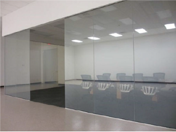
注意外部光線在玻璃中的反射。以下列出最佳到最差的四種照明條件:
ガラスに映り込む外部光の反射にご注意ください。以下に、最良から最悪までの 4 つの照明条件を示します:
Pay attention to how external light reflects off the glass. The four conditions, from best to worst:
| 條件 | 說明 | 霧狀程度 |
|---|---|---|
| 最差 | 僅在會議室外部的光線會導致光強不平衡 | 霧狀明顯增加 |
| 較佳 | 會議室外部的光線強度比裡面的高 | 輕微霧狀 |
| 最佳 | 會議室裡面和外部的光線強度均勻平衡,並在適當的距離充分漫射 | 最佳通透 |
| 暗室 | 黑暗狀態下(所有光線「關閉」) | 較小霧狀 |
| 条件 | 説明 | 白濁の程度 |
|---|---|---|
| 最悪 | 会議室の外側にのみ光源があり、光量バランスが崩れている | 白濁が顕著に増加 |
| 良好 | 会議室の外側の光量が内側より高い | わずかな白濁 |
| 最良 | 会議室の内側と外側の光量が均等にバランスし、適切な距離で十分に拡散している | 最も通透感が得られます |
| 暗室 | 暗い状態(すべての照明が「消灯」) | 白濁は少なめ |
| Condition | Description | Haze |
|---|---|---|
| Worst | Light only outside the room — unbalanced light intensity | Haze significantly increased |
| Better | Outside light brighter than inside | Slight haze |
| Best | Inside and outside evenly balanced and well-diffused at appropriate distance | Best clarity |
| Dark Room | All lights off | Low haze |
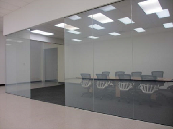
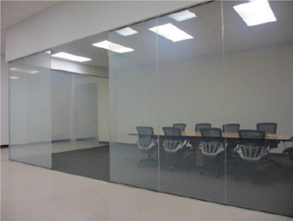
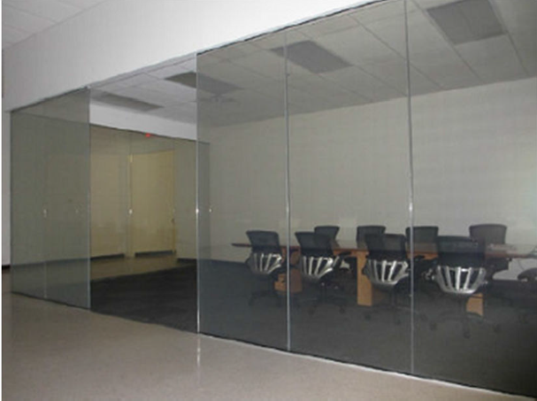
② 燈具型態與擺放建議
② 照明器具の形状と配置のご提案
② Fixture Type & Placement
除了「兩側光線平衡」之外,燈具的型態與照射方式,同樣會左右電控玻璃在透明狀態下的穿透觀感。電控玻璃即使切換到透明,表面仍帶有輕微殘霧與鏡面反光;當大面積、高亮度的均勻面光源或直射光正對玻璃時,會在玻璃表面形成炫光與霧化面紗,反而看不清玻璃後方。實際案場歸納如下:
「両側の光量バランス」に加えて、照明器具の形状と照射方法も、調光ガラスが透明状態にあるときの見え方を左右します。調光ガラスは透明に切り替えても、表面にはわずかな残留ヘイズと鏡面反射が残ります。大面積で高輝度の均一な面光源や直射光がガラスに正対すると、ガラス表面にグレアと白いベールが生じ、かえってガラスの向こう側が見えにくくなります。実際の現場から得られた知見は以下のとおりです:
Beyond the inside/outside balance above, the type of fixture and how it is aimed also govern how clearly you can see through the glass in its clear state. Even when switched clear, the glass keeps a slight residual haze and a glossy surface; a large, bright, uniform panel source — or direct light aimed straight at the glass — creates surface glare and a milky veil that obscures the view behind. Field experience is summarized below:
| 照明方式 | 對「透明穿透」的影響 |
|---|---|
| 線條燈(線性燈) | 光源細長、不形成大片反光面 → 穿透清晰 |
| 間接光 / 洗牆光 | 經天花、牆面漫射後柔和入射,殘霧不易被激發 → 視線通透 |
| 平板燈(面板燈) | 大面積均勻亮面直接映在玻璃上,形成炫光面紗 → 透明時反而看不清 |
| 光膜燈(背光膜) | 整片高亮背光,加重霧感與反光 → 穿透變差 |
| 直射光打在玻璃面 | 強光直射激發表面殘霧,產生霧化與反光 → 穿透變差 |
| 照明方式 | 「透明時の見通し」への影響 |
|---|---|
| ライン照明(線状照明) | 光源が細長く、大きな反射面をつくらない → 見通しが明瞭 |
| 間接照明 / ウォールウォッシャー | 天井・壁面で拡散した柔らかい光が入り、残留ヘイズが励起されにくい → 視線が通ります |
| パネルライト(面照明) | 大面積の均一な発光面がそのままガラスに映り込み、グレアのベールをつくる → 透明時にかえって見えにくくなります |
| 光膜照明(バックライトフィルム) | 面全体が高輝度のバックライトとなり、白濁感と反射を強める → 見通しが悪化します |
| ガラス面への直射光 | 強い直射光が表面の残留ヘイズを励起し、白濁と反射が生じる → 見通しが悪化します |
| Lighting | Effect on see-through (clear state) |
|---|---|
| Linear light | Slim source, no large reflective face → clear view |
| Indirect / wall-wash | Softly diffused off ceiling / wall; residual haze not excited → clear view |
| Flat panel light | Large uniform bright face reflects on the glass, forming a glare veil → view obscured when clear |
| Backlit light film | Full-panel bright backlight amplifies haze and reflection → poorer see-through |
| Direct light on the glass | Strong direct light excites surface haze, causing veiling and reflection → poorer see-through |
電極位置規劃建議
電極位置の計画に関するご提案
Electrode Placement Guidelines
當尺寸比超過 1:4 時(例:300 × 1500 mm)
寸法比が 1:4 を超える場合(例:300 × 1500 mm)
When aspect ratio > 1:4 (e.g. 300 × 1500 mm)
電極位置設計不得僅沿著短邊使用,可只沿著長邊使用,或在任意兩條邊上使用。
電極位置は短辺のみに沿わせることはできません。長辺のみに沿わせるか、任意の 2 辺に設けてください。
The electrode cannot be placed only on the short edge. It may be placed on the long edge alone, or along any two edges.
當尺寸比不超過 1:4 時(例:821 × 1952 mm)
寸法比が 1:4 を超えない場合(例:821 × 1952 mm)
When aspect ratio ≤ 1:4 (e.g. 821 × 1952 mm)
電極位置設計可以沿著任何一邊使用。
電極位置はいずれの辺に沿わせても構いません。
The electrode may be placed along any edge.
最大尺寸 1500 × 3500 mm 時
最大寸法 1500 × 3500 mm の場合
At maximum size 1500 × 3500 mm
必須使用兩邊電極位置設計,兩邊電極可以在任意兩邊使用。
2 辺への電極配置が必須です。2 辺の電極は任意の 2 辺に設けて構いません。
A two-edge electrode design is required. The two edges may be any pair of edges on the panel.
Busbar Model · 依玻璃尺寸選用
Busbar Model · ガラス寸法による選定
Busbar Model · Selection by Panel Size
原廠對不同尺寸的 PDLC / Startek R / EP 智能膜分別建議 4 種 busbar 配置(Model A / B / D / C),依玻璃高度(H)與高寬比(H : W)判斷。圖中黃色 / 藍色長條即電極(busbar)位置。
メーカーは、寸法の異なる PDLC / Startek R / EP スマートフィルムに対し、それぞれ 4 種類の busbar 配置(Model A / B / D / C)を推奨しています。ガラスの高さ(H)と縦横比(H : W)によって判断します。図中の黄色 / 青色の帯が電極(busbar)の位置です。
The film manufacturer recommends one of four busbar configurations (Model A / B / D / C) depending on panel height (H) and the height-to-width ratio (H : W). The yellow / blue strips in each illustration represent the electrode (busbar) location.
Model A · 頂端兩段(正負分極) 上端 2 分割(正負分極)Top edge (split + / −)
PDLC:H < 2.7m 且 H/W < 7
Startek R:H < 1.5m
EP(SPD):H < 2.7m 且 H/W < 7
PDLC:H < 2.7m かつ H/W < 7
Startek R:H < 1.5m
EP(SPD):H < 2.7m かつ H/W < 7
PDLC: H < 2.7m and H/W < 7
Startek R: H < 1.5m
EP (SPD): H < 2.7m and H/W < 7
Model B · 頂底兩端 上端・下端の 2 辺Top & bottom edges
PDLC:2.7m ≤ H < 3.3m 或 H < 2.7m 但 H/W ≥ 7
Startek R:不適用
EP(SPD):2.7m ≤ H < 3.3m 或 H/W ≥ 7
PDLC:2.7m ≤ H < 3.3m、または H < 2.7m かつ H/W ≥ 7
Startek R:適用外
EP(SPD):2.7m ≤ H < 3.3m、または H/W ≥ 7
PDLC: 2.7m ≤ H < 3.3m, or H < 2.7m with H/W ≥ 7
Startek R: Not applicable
EP (SPD): 2.7m ≤ H < 3.3m, or H/W ≥ 7
Model D · 頂底兩端(各自分極) 上端・下端の 2 辺(それぞれ分極)Top & bottom (each split + / −)
PDLC:3.3m ≤ H < 5m 或 H < 3.3m 但 H/W ≥ 7
Startek R:1.5m ≤ H < 3m 或 H < 1.5m
EP(SPD):3.3m ≤ H < 5m 或 H/W ≥ 7
PDLC:3.3m ≤ H < 5m、または H < 3.3m かつ H/W ≥ 7
Startek R:1.5m ≤ H < 3m、または H < 1.5m
EP(SPD):3.3m ≤ H < 5m、または H/W ≥ 7
PDLC: 3.3m ≤ H < 5m, or H < 3.3m with H/W ≥ 7
Startek R: 1.5m ≤ H < 3m, or H < 1.5m
EP (SPD): 3.3m ≤ H < 5m, or H/W ≥ 7
Model C · 單側邊(上下分極) 片側の辺(上下で分極)One side edge (split + / −)
PDLC:H ≥ 5m 或 H < 5m 但 H/W ≥ 7
Startek R:H ≥ 3m 或 H ≤ 3m 但 H/W ≥ 7
EP(SPD):H ≥ 5m 或 H/W ≥ 7
PDLC:H ≥ 5m、または H < 5m かつ H/W ≥ 7
Startek R:H ≥ 3m、または H ≤ 3m かつ H/W ≥ 7
EP(SPD):H ≥ 5m、または H/W ≥ 7
PDLC: H ≥ 5m, or H < 5m with H/W ≥ 7
Startek R: H ≥ 3m, or H ≤ 3m with H/W ≥ 7
EP (SPD): H ≥ 5m, or H/W ≥ 7
ITO 表面阻值要求(出貨前處理 / 拭膠後檢測)
ITO 表面抵抗値の要件(出荷前処理 / シーリング材拭取り後の検査)
ITO Sheet Resistance (post-cleaning QC)
| 膜種 | 清潔方式 | 方阻 (Ω) |
|---|---|---|
| PDLC | 無塵紙輕拭 polymer,避免傷 ITO | < 300 Ω(< 200 Ω 最佳) |
| Startek R(PNLC / DLC) | 因多一層絕緣層,先除聚合物後,用沾無水酒精的無塵紙稍施力擦淨絕緣層 | < 300 Ω(150–220 Ω 最佳) |
| EP(SPD) | 無塵紙輕拭,注意不傷 ITO | < 300 Ω(一般 100–300 Ω) |
| フィルム種別 | 清掃方法 | シート抵抗 (Ω) |
|---|---|---|
| PDLC | クリーンペーパーでポリマーを軽く拭き取り、ITO を傷めないようにします | < 300 Ω(< 200 Ω が最適) |
| Startek R(PNLC / DLC) | 絶縁層が 1 層多いため、ポリマーを除去した後、無水アルコールを含ませたクリーンペーパーでやや力を入れて絶縁層を拭き取ります | < 300 Ω(150〜220 Ω が最適) |
| EP(SPD) | クリーンペーパーで軽く拭き取り、ITO を傷めないようご注意ください | < 300 Ω(通常 100〜300 Ω) |
| Film | Cleaning | Sheet R (Ω) |
|---|---|---|
| PDLC | Wipe polymer gently with dust-free paper; ITO is fragile | < 300 Ω (< 200 Ω ideal) |
| Startek R (PNLC / DLC) | Has an extra insulating layer above ITO; after removing polymer, wipe the insulating layer firmly with dust-free paper moistened with anhydrous ethanol | < 300 Ω (150–220 Ω ideal) |
| EP (SPD) | Wipe gently with dust-free paper; protect the ITO | < 300 Ω (typically 100–300 Ω) |
電極設計與穿透率關係(合約條款補充)
電極設計と透過率の関係(契約条項の補足)
Electrode Design vs. Transmittance (Contract Supplement)
變壓器 / 遙控器說明
トランス・リモコンについて
Transformer & Remote

STARTEK 專用變壓器 + 遙控器
STARTEK 専用トランス + リモコン
STARTEK Dedicated Transformer + Remote
STARTEK 專用變壓器
- 尺寸 110 × 46 × 179 mm,1.6 kg
- 輸入 110 VAC 或 220 VAC(非全電壓,預設為 110V 變壓器)
- 輸出 65 VAC
- 瓦數 100 W
- 2 年保固,CE 認證
STARTEK 無線遙控器
- 無線控制(433 MHz)
- 電池 12 VDC
- 控制距離 > 25 m
- 尺寸 120 × 46 × 14 mm,80 g
STARTEK 専用トランス
- 寸法 110 × 46 × 179 mm、1.6 kg
- 入力 110 VAC または 220 VAC(フルレンジ入力ではありません。標準は 110V 仕様)
- 出力 65 VAC
- 消費電力 100 W
- 保証 2 年、CE 認証取得
STARTEK ワイヤレスリモコン
- ワイヤレス制御(433 MHz)
- 電池 12 VDC
- 制御距離 > 25 m
- 寸法 120 × 46 × 14 mm、80 g
STARTEK Dedicated Transformer
- Size 110 × 46 × 179 mm, 1.6 kg
- Input 110 VAC or 220 VAC (not universal input; 110V by default)
- Output 65 VAC
- Power 100 W
- 2-year warranty, CE certified
STARTEK Wireless Remote
- Wireless control (433 MHz)
- Battery 12 VDC
- Range > 25 m
- Size 120 × 46 × 14 mm, 80 g
可調壓遙控器(透光度可調)
電圧調整リモコン(透過度の調整が可能)
Dimming Remote (Adjustable Transparency)
不只全開/全關 — 搭配可調式電源,可透過遙控器與面板旋鈕無段調整玻璃透光度,並能設定開關時的漸變過度與自動展示模式。
全開/全閉だけではありません —— 調光対応の電源と組み合わせることで、リモコンとパネルのつまみからガラスの透過度を無段階に調整でき、切替時のグラデーション(フェード)や自動デモモードの設定も可能です。
More than just on/off — paired with the adjustable power supply, transparency can be tuned steplessly via the remote and panel knob, with gradual fade transitions and an auto-demo mode.

調光膜可調式電源
- 輸入 AC 110V / 220V
- 輸出 AC 48V / 60V
- 額定功率 50W / 100W / 200W
- 控制方式 線控旋鈕 / 無線遙控 / RS485
- 工作溫度 −10 ~ 50°C
- 過壓 / 過載 / 短路保護
可調壓遙控器
- 上鍵 — 增加透明度
- 中鍵 — 開 / 關
- 下鍵 — 增加霧度(減少透明度)
- 長按開關鍵進入漸變 / 自動展示,並可調整週期
- PAIR 鍵配對,可重新學習綁定
調光フィルム用 調光対応電源
- 入力 AC 110V / 220V
- 出力 AC 48V / 60V
- 定格出力 50W / 100W / 200W
- 制御方式 有線つまみ / ワイヤレスリモコン / RS485
- 動作温度 −10 〜 50°C
- 過電圧 / 過負荷 / 短絡保護
電圧調整リモコン
- 上ボタン — 透明度を上げる
- 中ボタン — ON / OFF
- 下ボタン — 白濁度を上げる(透明度を下げる)
- ON/OFF ボタンの長押しでグラデーション / 自動デモモードに入り、周期の調整も可能
- PAIR ボタンでペアリング。再学習による紐付け直しが可能
Adjustable Power Supply
- Input AC 110V / 220V
- Output AC 48V / 60V
- Rated power 50W / 100W / 200W
- Control: panel knob / wireless remote / RS485
- Operating temperature −10 to 50°C
- Over-voltage / overload / short-circuit protection
Dimming Remote
- Up — increase transparency
- Middle — on / off
- Down — increase haze (decrease transparency)
- Hold the on/off key for fade / auto-demo mode, with adjustable cycle
- PAIR button for pairing and re-learning
分點多點控制變壓器(分區開關)
多点制御対応トランス(ゾーン別スイッチ)
Multi-Zone Control Transformer
一台變壓器最多分 6 路,可同步或個別控制多片玻璃 — 遙控器數字鍵對應不同分區,單片獨立開關或一鍵全開/全關。此款為分區開關控制,不調整透光度(不可調壓)。
1 台のトランスで最大 6 系統に分岐でき、複数のガラスを一括または個別に制御できます —— リモコンの数字ボタンが各ゾーンに対応し、1 枚ごとの個別 ON/OFF、ワンタッチでの全開/全閉が可能です。本機種はゾーン別のスイッチ制御であり、透過度の調整はできません(電圧調整不可)。
One transformer drives up to 6 channels, switching multiple glass panels together or independently — the remote's numbered keys map to different zones for single-panel or all-on / all-off control. This is zone on/off control and does not adjust transparency (non-dimming).

多點式控制變壓器
- 6 路輸出,各路可同步或個別開關
- 輸入 110 VAC 或 220 ~ 240 VAC
- 輸出 48V / 68V
- 額定功率 50W / 100W / 200W
- 頻率 45 ~ 70 Hz
- 過壓 / 過載保護
- 分區開關控制(不可調壓)
分區遙控器
- 鍵 1 ~ 6 — 對應第 1 ~ 6 路 開 / 關
- 鍵 7 — 全部開
- 鍵 8 — 全部關
- 面板開關:按壓開關;旋鈕調整開關漸變速度(非透光度);長按 10 秒切換輸出路數
- PAIR 鍵配對,可重新學習綁定
多点制御対応トランス
- 6 系統出力、各系統を一括または個別に ON/OFF 可能
- 入力 110 VAC または 220 〜 240 VAC
- 出力 48V / 68V
- 定格出力 50W / 100W / 200W
- 周波数 45 〜 70 Hz
- 過電圧 / 過負荷保護
- ゾーン別スイッチ制御(電圧調整不可)
ゾーンリモコン
- ボタン 1 〜 6 — 第 1 〜 6 系統の ON / OFF に対応
- ボタン 7 — 全灯 ON
- ボタン 8 — 全灯 OFF
- パネルスイッチ:押して ON/OFF。つまみで切替のフェード速度を調整(透過度ではありません)。10 秒長押しで出力系統数を切替
- PAIR ボタンでペアリング。再学習による紐付け直しが可能
Multi-Channel Control Transformer
- 6-channel output, each channel switched together or independently
- Input 110 VAC or 220–240 VAC
- Output 48V / 68V
- Rated power 50W / 100W / 200W
- Frequency 45–70 Hz
- Over-voltage / overload protection
- Zone on/off control (non-dimming)
Zone Remote
- Keys 1–6 — channels 1–6 on / off
- Key 7 — all on
- Key 8 — all off
- Panel switch: press to toggle; rotate to set switching fade speed (not transparency); hold 10s to change the active channel
- PAIR button for pairing and re-learning
明基 AWS100 專用電源 + 遙控器
明基 AWS100 専用電源 + リモコン
BenQ AWS100 Power Supply + Remote
搭配明基 PDLC 系列(STARTEK 2 / 3 / EX 系列)電控玻璃使用,明基官方 1 年保固。
明基 PDLC シリーズ(STARTEK 2 / 3 / EX シリーズ)調光ガラス用。明基メーカー保証 1 年。
Used with the BenQ PDLC series (STARTEK 2 / 3 / EX). BenQ-official 1-year warranty.


PDLC 專用電源
- 尺寸 69 W × 242 L × 44.54 H mm(公差 ±0.2 mm)
- 輸入 100 ~ 240 VAC(國際通用)
- 輸出 48 VAC(低電壓設計)
- 12 階透光度調整
- 支援群組配對(一對多 / 多對一)
- CB / CE / CCC / BSMI 安規通過
- 操作環境 0 ~ 40°C,20 ~ 90% RH
- 1 年保固
無線遙控器
- 頻率 433.92 MHz(穿牆能力佳、低電磁波)
- 無障礙 + 干擾條件下控制距離 達 50 m
- 電池 CR2032,正常使用 3 年
- ON / OFF 一鍵全開 / 全關,△ / ▽ 透光度增 / 減
- 附壁掛底座,可鎖牆固定;遙控器可取出 / 扣回底座
PDLC 専用電源
- 寸法 69 W × 242 L × 44.54 H mm(公差 ±0.2 mm)
- 入力 100 〜 240 VAC(国際汎用)
- 出力 48 VAC(低電圧設計)
- 12 段階の透過度調整
- グループペアリング対応(1 対多 / 多対 1)
- CB / CE / CCC / BSMI 安全規格適合
- 使用環境 0 〜 40°C、20 〜 90% RH
- 保証 1 年
ワイヤレスリモコン
- 周波数 433.92 MHz(壁越しの到達性が良く、電磁波が少ない)
- 障害物・干渉のない条件での制御距離 最大 50 m
- 電池 CR2032、通常使用で 3 年
- ON / OFF ワンタッチで全開 / 全閉、△ / ▽ 透過度の増 / 減
- 壁掛けベース付属。壁面に固定でき、リモコンは着脱可能
PDLC Power Supply
- Size 69 W × 242 L × 44.54 H mm (tolerance ±0.2 mm)
- Input 100–240 VAC (worldwide)
- Output 48 VAC (low-voltage design)
- 12-level transparency adjustment
- Group pairing (one-to-many / many-to-one)
- CB / CE / CCC / BSMI certified
- Operating environment 0–40°C, 20–90% RH
- 1-year warranty
Wireless Remote
- Frequency 433.92 MHz (good wall penetration, low EMF)
- Range up to 50 m in clear, interference-free conditions
- CR2032 battery, ~3-year typical life
- ON / OFF all-on / all-off, △ / ▽ transparency up / down
- Includes a screw-fixed wall dock; the remote detaches and re-docks
 圖|BenQ AWS100 無線遙控器 — ON / OFF 與 △▽ 透光度調整
 圖|BenQ AWS100 完整面板含壁掛底座 — 底座鎖牆固定,遙控器可取出 / 扣回
図|BenQ AWS100 ワイヤレスリモコン — ON / OFF と △▽ による透過度調整
図|BenQ AWS100 パネル一式(壁掛けベース付)— ベースを壁面に固定し、リモコンは着脱できます
Fig.|BenQ AWS100 wireless remote — ON / OFF and △▽ transparency control
Fig.|BenQ AWS100 complete panel with wall dock — screw-fixed to the wall; remote detaches / re-docks
圖|BenQ AWS100 完整面板含壁掛底座 — 底座鎖牆固定,遙控器可取出 / 扣回
図|BenQ AWS100 ワイヤレスリモコン — ON / OFF と △▽ による透過度調整
図|BenQ AWS100 パネル一式(壁掛けベース付)— ベースを壁面に固定し、リモコンは着脱できます
Fig.|BenQ AWS100 wireless remote — ON / OFF and △▽ transparency control
Fig.|BenQ AWS100 complete panel with wall dock — screw-fixed to the wall; remote detaches / re-docks明基 AWS100 配對流程(首次安裝 / 換新)
明基 AWS100 ペアリング手順(初回設置 / 交換時)
BenQ AWS100 Pairing (First Install / Replacement)
- 燈號確認 — 先確認接線正確,移除遙控器電池保護膜,按 ON 鍵 — 亮橘燈代表正常。
- 進入配對狀態 — 連續按住電源連接鈕 5 秒,直到 LED 閃綠燈再放開。
- 配對遙控器 — 在 15 秒內按下遙控器 ON 鍵 3 秒。
- 結束配對 — 再按一次電源連接鈕,停止閃爍即完成。
- ランプの確認 —— まず結線が正しいことを確認し、リモコンの電池絶縁シートを外して ON ボタンを押します。オレンジ色に点灯すれば正常です。
- ペアリングモードへ移行 —— 電源側の接続ボタンを 5 秒間押し続け、LED が緑色に点滅したら離します。
- リモコンのペアリング —— 15 秒以内に、リモコンの ON ボタンを 3 秒間押します。
- ペアリングの終了 —— 電源側の接続ボタンをもう一度押し、点滅が止まれば完了です。
- LED check — Verify wiring, remove the remote's battery insulator, press ON — an orange light indicates normal status.
- Enter pairing mode — Hold the power-pairing button for 5 seconds until the LED flashes green, then release.
- Pair the remote — Within 15 seconds, press the remote's ON button for 3 seconds.
- Exit pairing — Press the power-pairing button once more; pairing is complete when the LED stops flashing.
- 按 ON 鍵不亮:電池沒電,需更換 CR2032
- 按 ON 鍵快閃:電池即將沒電,需更換
- 按 ON 鍵閃一次:正常動作
- 遙控器按下後,電源 LED 應閃一下;若不閃,重新配對
- ON ボタンを押しても点灯しない:電池切れです。CR2032 を交換してください
- ON ボタンを押すと速く点滅する:電池残量が少なくなっています。交換してください
- ON ボタンを押すと1 回点滅する:正常動作です
- リモコン操作時、電源側の LED が 1 回点滅するはずです。点滅しない場合は再度ペアリングしてください
- ON button no light: battery dead, replace CR2032
- ON button rapid flashing: battery low, needs replacing
- ON button single flash: normal operation
- After pressing the remote, the power LED should flash once; if not, re-pair
智慧家庭整合(手機 / 語音 / 門片與存在感測連動)
スマートホーム連携(スマホ / 音声 / ドア・人感センサー連動)
Smart Home Integration (App / Voice / Door & Presence Triggered)
除了 §10 的實體遙控器之外,電控玻璃也可以接入智慧家庭系統,用手機 App、語音助理或自動化規則控制。作法很單純:把 STARTEK 變壓器的市電端插在智慧插座上,由智慧家庭系統控制這個插座的通電/斷電,即等同開關電控玻璃 — 不需要改動變壓器、二次線或玻璃本體的任何配置。
§10 の物理リモコンに加えて、調光ガラスはスマートホームシステムに接続し、スマホアプリ、音声アシスタント、または自動化ルールで制御できます。方法は単純です:STARTEK トランスの商用電源側をスマートプラグに挿すだけで、スマートホームシステムがそのプラグの通電/断電を制御することが、そのまま調光ガラスの ON/OFF になります —— トランス、二次側配線、ガラス本体の構成を変更する必要は一切ありません。
Beyond the physical remote described in §10, smart glass can be brought into a smart-home system and controlled from a phone app, a voice assistant, or an automation rule. The method is simple: plug the STARTEK transformer's mains lead into a smart plug and let the smart-home system switch that plug on and off. No change is needed to the transformer, the secondary wiring, or the glass itself.
三種常見情境
よくある 3 つのケース
Three Common Scenarios
情境 A|手機與語音控制 — 最小組合是「智慧插座 + 網關」。插座負責通斷變壓器的市電,網關負責把插座接上手機與語音生態;若想在牆上保留一個實體按鍵,再加一顆免佈線的無線按鍵即可。
ケース A|スマホと音声による制御 —— 最小構成は「スマートプラグ + ゲートウェイ」です。プラグがトランスの商用電源を入切し、ゲートウェイがプラグをスマホと音声のエコシステムに接続します。壁面に物理ボタンを残したい場合は、配線不要のワイヤレスボタンを 1 つ追加してください。
Scenario A|Phone & voice control — The minimum set is a smart plug plus a hub. The plug switches mains power to the transformer; the hub connects the plug to the phone app and voice ecosystem. If a physical wall button is still wanted, add a wire-free wireless switch.
情境 B|門片開啟連動 — 玻璃裝在門片上、希望「門一打開就自動作動」時,在門扇上加一顆多維感測器。感測器偵測到門的開合姿態變化後,透過網關觸發自動化規則,切換插座的通斷。
ケース B|ドアの開閉との連動 —— ガラスを扉に取り付け、「扉を開けたら自動で動作させたい」場合は、扉に多機能センサーを 1 つ追加します。センサーが扉の開閉による姿勢変化を検知すると、ゲートウェイ経由で自動化ルールが起動し、プラグの入切を切り替えます。
Scenario B|Door-triggered — When the glass is in a door leaf and should switch automatically as the door opens, add a multi-state sensor to the leaf. The sensor detects the door's change of orientation, and the hub runs an automation rule that switches the plug.
情境 C|人體存在感測(會議室自動霧化) — 會議室、洽談室這種「有人就要隱私、沒人就要通透」的空間,可在室內加一顆人體存在感測器。感測器偵測到有人進入後,透過網關觸發自動化規則切換插座,玻璃自動霧化;確認室內無人後再切回透明,讓空間在多數時間維持通透明亮。與一般紅外線移動偵測不同的是,毫米波存在感測連「坐著不動、只有呼吸起伏」的人也判得出來,開會開到一半不會因為久坐沒動作就自己變透明。
ケース C|人体存在検知(会議室の自動不透明化) —— 会議室や商談室のような「人がいればプライバシーが必要、いなければ開放的にしたい」空間では、室内に人体存在センサーを 1 つ設置します。人の入室を検知するとゲートウェイ経由で自動化ルールが起動してプラグを切り替え、ガラスが自動的に不透明になります。室内に人がいないと判定されると透明に戻り、多くの時間を通透感のある明るい空間として保てます。一般的な赤外線の動体検知と異なり、ミリ波による存在検知は「座ったまま動かず、呼吸による動きしかない」人も判定できるため、会議の途中で動かずにいたからといって勝手に透明に戻ることがありません。
Scenario C|Human presence sensing (meeting room auto-frosting) — In meeting and consultation rooms, where privacy is wanted whenever the room is occupied and openness the rest of the time, add a human presence sensor inside the room. When it detects someone entering, the hub runs an automation rule that switches the plug and the glass frosts automatically; once the room is confirmed empty it returns to clear, so the space stays open and bright most of the time. Unlike ordinary infrared motion detection, mmWave presence sensing also registers a person sitting still — breathing is enough — so the glass will not clear itself mid-meeting simply because nobody moved.
- FP300 — 電池供電、免佈線,PIR +毫米波雙感測,偵測範圍 120°。裝設位置沒有電源、或不想為了一顆感測器另拉線時選它;也內建光線/溫濕度感測,可再搭出「日照太強才霧化」這類規則。
- FP1E — 需 5V/1A USB 常時供電,純毫米波,偵測距離可達 6 m、視野 120°(近距離 180°)。空間較大、或希望偵測最穩定時選它。
- 兩者都是偵測「空間裡有沒有人」,與 §10 的遙控器、情境 A 的手機語音可以並存 — 自動化只是多一個觸發來源,不會把手動控制拿掉。
- FP300 —— 電池駆動で配線不要。PIR +ミリ波のデュアルセンシング、検知範囲 120°。設置位置に電源がない場合や、センサー 1 つのために配線を引きたくない場合に適します。照度/温湿度センサーも内蔵しており、「日射が強いときだけ不透明化する」といったルールも組めます。
- FP1E —— 5V/1A USB の常時給電が必要。ミリ波単独で、検知距離は最大 6 m、視野 120°(近距離では 180°)。空間が広い場合や、検知を最も安定させたい場合に適します。
- いずれも「空間に人がいるかどうか」を検知するものです。§10 のリモコンやケース A のスマホ・音声制御と併用でき、自動化は触発の手段が 1 つ増えるだけで、手動操作がなくなるわけではありません。
- FP300 — battery powered and wire-free, combining PIR with mmWave, 120° coverage. Choose it where the mounting position has no power, or where running a cable just for a sensor is unwelcome. It also carries light, temperature, and humidity sensing, which allows rules such as "frost only when the sun is strong".
- FP1E — requires permanent 5V / 1A USB power, mmWave only, with detection up to 6 m and a 120° field of view (180° at close range). Choose it for larger rooms or where the most stable detection is wanted.
- Both sense whether the room is occupied, and coexist with the remote in §10 and the phone/voice control of Scenario A — automation adds a trigger, it does not remove manual control.
耐用性設計建議(非使用時段排程霧化)
耐久性を高める設計のご提案(不使用時間帯のスケジュール不透明化)
Durability Design Guidance (Scheduled Frosting Outside Working Hours)
電控玻璃接進智慧家庭之後,最值得設定的一條規則不是「怎麼開」,而是「什麼時候讓它休息」。STARTEK 建議在網關上另外排一組時間規則:下班時段、深夜、週末與國定假日這類確定無人使用的時間,自動把電控玻璃切回霧化(斷電)狀態。這件事只花設定時的十分鐘,但直接影響玻璃能用幾年。
調光ガラスをスマートホームに接続したあと、最も設定する価値があるルールは「どう点けるか」ではなく「いつ休ませるか」です。STARTEK では、ゲートウェイに時間ルールをもう 1 組設定することをお勧めします:就業時間外、深夜、週末、祝日など、確実に使用されない時間帯には、自動的に不透明(断電)状態に戻す設定です。設定にかかるのは 10 分ほどですが、ガラスを何年使えるかに直接影響します。
Once the glass is on a smart-home system, the setting that matters most is not how to switch it on, but when to let it rest. STARTEK recommends adding a separate time-based rule on the hub: outside working hours, overnight, and at weekends and public holidays — any period the room is certainly unused — return the glass automatically to its frosted (unpowered) state. It takes ten minutes to configure and directly affects how many years the glass lasts.
- 使用年限是有限資源,切一次少一次。依附錄 D 的第三方檢測,PDLC 以 80,000 次開關切換為壽命基準,日常使用可對應到 10 年以上的使用強度。但若存在感測沒有設延遲,一間人來人往的會議室一天就可能被觸發上百次 — 那是日常使用強度的好幾倍,累計切換次數會被快速消耗掉。
- 霧化就是一般 PDLC 的靜止狀態。一般 PDLC 是通電透明、斷電霧化,非使用時段排程斷電等同讓液晶層停止工作,同時省下變壓器的待機耗電(每組 100 W,見 §10)。
- 「謹慎使用」是 25 年平均使用壽命的前提。§01 標示的平均使用壽命以謹慎使用為條件;排程休息是這個條件裡最容易落實、也最不需要使用者配合的一條。
- 使用可能な回数は有限で、1 回切り替えるごとに減っていきます。附録 D の第三者試験によれば、PDLC は 80,000 回の ON/OFF 切替を寿命の基準としており、日常的なご使用において 10 年以上の使用強度に対応します。しかし存在センサーに遅延を設定していないと、人の出入りが多い会議室では 1 日に数百回作動することもあります —— これは日常的な使用強度の数倍にあたり、累計の切替回数が急速に消費されます。
- 不透明状態は、通常の PDLC にとっての静止状態です。通常の PDLC は通電で透明・断電で不透明となるため、不使用時間帯に断電をスケジュールすることは液晶層を休ませることと同義であり、同時にトランスの待機電力(1 組あたり 100 W、§10 参照)も削減できます。
- 「丁寧なご使用」が耐用性の前提です。§01 に記載した使用強度は、丁寧にご使用いただくことを条件としています。スケジュールによる休止は、その条件のなかで最も実行しやすく、使用者の方に負担をかけない方法です。
- Service life is a finite resource — every switch spends some of it. Per the third-party testing in Appendix D, PDLC life is benchmarked at 80,000 ON/OFF cycles, corresponding to more than ten years of ordinary use. But if presence-based automation is configured without a delay, a busy meeting room can be triggered hundreds of times a day — several times ordinary usage intensity — and those cycles are consumed far faster.
- Frosted is the resting state of standard PDLC. Standard PDLC is clear when powered and frosted when unpowered, so a scheduled power-off outside working hours stops the liquid-crystal layer working and saves the transformer's standby consumption at the same time (100 W per unit, see §10).
- "Careful use" is the condition attached to the 25-year average service life. The average life quoted in §01 assumes careful use; a rest schedule is the easiest part of that condition to deliver, and the only one that asks nothing of the end user.
| 時段/情形 | 建議設定 | 為什麼 |
|---|---|---|
| 平日下班後至隔日上班前 | 排程自動霧化(斷電),例如 19:00 → 隔日 08:00 | 無人使用的十幾個小時不再累計通電時數 |
| 週末、國定假日 | 全日排程霧化 | 整段空檔一次涵蓋,不必靠人記得關 |
| 連假、年度歲修、長期空置 | 直接關閉該區智慧插座 | 玻璃與變壓器一併停止工作 |
| 存在感測自動化 | 設「持續無人達 10–15 分鐘才切換」的延遲 | 避免短暫進出、清潔人員經過造成整天頻繁切換 |
| 排程與感測衝突時 | 讓排程優先(非使用時段停用感測觸發) | 下班後不會因為有人經過就整晚反覆切換 |
| 時間帯/状況 | 推奨設定 | 理由 |
|---|---|---|
| 平日の就業終了後から翌朝の始業前まで | 自動で不透明(断電)にスケジュール。例:19:00 → 翌 08:00 | 使用されない十数時間について通電時間が累積しなくなります |
| 週末、祝日 | 終日、不透明にスケジュール | 空き時間をまとめてカバーでき、人が消し忘れる心配がありません |
| 連休、年次点検、長期の空室 | 該当エリアのスマートプラグを直接オフに | ガラスとトランスの両方を停止できます |
| 存在センサーによる自動化 | 「不在が 10〜15 分続いてから切り替える」遅延を設定 | 短時間の出入りや清掃担当者の通過によって、1 日中頻繁に切り替わることを防ぎます |
| スケジュールとセンサーが競合する場合 | スケジュールを優先(不使用時間帯はセンサーによる作動を無効化) | 就業時間外に人が通るたび、一晩中繰り返し切り替わることを防ぎます |
| Period / Situation | Recommended Setting | Why |
|---|---|---|
| Weekday evenings until the next morning | Schedule automatic frosting (power off), e.g. 19:00 → 08:00 | Stops accumulating powered hours across a dozen unused hours |
| Weekends and public holidays | Frosted for the whole day | Covers the entire gap at once, with nobody needing to remember |
| Long holidays, annual shutdown, vacant periods | Switch the zone's smart plug off entirely | Glass and transformer both stop working |
| Presence-based automation | Require 10–15 minutes of continuous vacancy before switching | Prevents brief entries and passing cleaners from causing all-day switching |
| When schedule and sensor conflict | Let the schedule win — disable sensor triggers outside working hours | Someone walking past after hours will not switch the glass all night |
配件規格
付属品仕様
Accessory Specifications

Aqara 智能插座
- 產品型號 ZNCZ12LM(台灣規格)
- 無線協議 Zigbee — 需搭配網關,無法單獨連 Wi-Fi
- 額定 100–125 VAC / 15 A / 1875 W,60 Hz
- 尺寸 67 × 47 × 35 mm,88 g
- 過熱/過載自動斷電,插孔附安全保護門
- 具電量統計功能
- 工作溫度 −10 ~ +40°C
- 支援 Aqara Home、Apple Home、Google Assistant

Aqara M100 網關
- 產品型號 HM-G02D
- 支援 Zigbee + Thread 雙協議,可作 Matter Controller/Thread Border Router/Matter Bridge
- 供電 USB 5V 0.5A(需輸出 2.5 W 以上的 USB 埠)
- 尺寸 108 × 30 × 8 mm
- 需 2.4 GHz Wi-Fi
- 原廠建議子設備上限 40 個(其中 Zigbee 20 個)
- 支援 Apple Home、Google Home、Amazon Alexa、SmartThings、Home Assistant

Aqara Mini 無線按鍵
- 產品型號 WXKG11LM
- 無線協議 Zigbee — 需搭配網關
- 單按/雙按/長按可各自綁定不同動作
- 尺寸 45 × 45 × 12 mm,電池 CR2032
- 免佈線,背膠直接貼牆,不需開孔埋線盒
- 工作溫度 −10 ~ +55°C
- Wi-Fi 斷線時仍可透過 Zigbee 本地控制

Aqara P100 多維感測器
- 產品型號 DWZTCGQ11LM
- 無線協議 Thread/Zigbee 雙協議+藍牙
- 九軸感測(三軸加速度+三軸陀螺儀+三軸地磁),可辨識開合、傾斜、移動、震動等事件
- 尺寸 45 × 31 × 13 mm,電池 CR2450 × 1
- 電池續航 Zigbee 模式約 2 年、Thread 模式約 1.5 年
- 工作溫度 −10 ~ +55°C
- 包裝含背膠 × 2

Aqara FP300 存在感測器
- 產品型號 PS-S04D
- PIR +毫米波(mmWave)雙感測,靜坐不動也偵測得到
- 無線協議 Thread/Zigbee 雙協議+藍牙;Thread 模式可免網關直連 Apple Home 與 Matter
- 偵測範圍 120°
- 內建光線、溫度、濕度感測,可組合出「日照強才霧化」這類規則
- 尺寸 42 × 42 × 50 mm,電池 CR2450 × 2
- 電池續航 Zigbee 模式約 3 年、Thread 模式約 2 年(原廠實驗室條件,實際依觸發頻率而定)
- 工作溫度 −10 ~ 50°C,濕度 0–95% RH 無凝結
- 免佈線:背膠/磁吸/螺絲皆可;安裝高度超過 2 m 建議鎖螺絲
- 包裝含金屬安裝板 × 1、螺絲套件 × 1

Aqara FP1E 存在感測器
- 產品型號 PS-S03D
- 純毫米波(mmWave)感測,雷達工作頻率 60–61 GHz
- 偵測距離達 6 m,視野 120°(近距離可達 180°);可於 App 內設定 0–6 m
- 無線協議 Zigbee 3.0 — 需搭配網關
- 供電 5V⎓1A(USB-A,附 2 m 電源線)— 需常時供電,不可接在會被排程斷電的插座上
- AI 空間學習自動調整靈敏度,可濾除小型寵物、掃地機器人等干擾源
- 尺寸 57 × 50 × 37 mm,工作溫度 −10 ~ 40°C
- 安裝:磁鐵安裝座/雙面膠/鑽孔,可裝牆面、牆角或天花板
- 透過網關以 Matter over Bridge 支援 Apple Home、Google Home、Alexa、SmartThings、Home Assistant
Aqara スマートプラグ
- 型番 ZNCZ12LM(台湾仕様)
- 無線プロトコル Zigbee — ゲートウェイが必要で、単体では Wi-Fi に接続できません
- 定格 100〜125 VAC / 15 A / 1875 W、60 Hz
- 寸法 67 × 47 × 35 mm、88 g
- 過熱/過負荷時の自動遮断、差込口にシャッター付
- 電力量計測機能付
- 動作温度 −10 〜 +40°C
- Aqara Home、Apple Home、Google Assistant に対応
Aqara M100 ゲートウェイ
- 型番 HM-G02D
- Zigbee + Thread のデュアルプロトコル対応。Matter Controller/Thread Border Router/Matter Bridge として動作します
- 電源 USB 5V 0.5A(2.5 W 以上を出力できる USB ポートが必要)
- 寸法 108 × 30 × 8 mm
- 2.4 GHz Wi-Fi が必要
- メーカー推奨の子機上限は 40 台(うち Zigbee 20 台)
- Apple Home、Google Home、Amazon Alexa、SmartThings、Home Assistant に対応
Aqara Mini ワイヤレスボタン
- 型番 WXKG11LM
- 無線プロトコル Zigbee — ゲートウェイが必要
- シングルクリック/ダブルクリック/長押しにそれぞれ別の動作を割り当て可能
- 寸法 45 × 45 × 12 mm、電池 CR2032
- 配線不要。両面テープで壁に直接貼付でき、開口やスイッチボックスの埋設が不要です
- 動作温度 −10 〜 +55°C
- Wi-Fi が切断されても Zigbee によるローカル制御が可能
Aqara P100 多機能センサー
- 型番 DWZTCGQ11LM
- 無線プロトコル Thread/Zigbee デュアル+ Bluetooth
- 9 軸センシング(3 軸加速度+3 軸ジャイロ+3 軸地磁気)。開閉・傾き・移動・振動などのイベントを識別できます
- 寸法 45 × 31 × 13 mm、電池 CR2450 × 1
- 電池寿命 Zigbee モードで約 2 年、Thread モードで約 1.5 年
- 動作温度 −10 〜 +55°C
- 両面テープ × 2 同梱
Aqara FP300 存在センサー
- 型番 PS-S04D
- PIR +ミリ波(mmWave)デュアルセンシング。座ったまま動かない人も検知できます
- 無線プロトコル Thread/Zigbee デュアル+ Bluetooth。Thread モードではゲートウェイなしで Apple Home および Matter に直接接続できます
- 検知範囲 120°
- 照度・温度・湿度センサーを内蔵。「日射が強いときだけ不透明化する」といったルールを組めます
- 寸法 42 × 42 × 50 mm、電池 CR2450 × 2
- 電池寿命 Zigbee モードで約 3 年、Thread モードで約 2 年(メーカー試験室条件。実際は作動頻度によります)
- 動作温度 −10 〜 50°C、湿度 0〜95% RH 結露なきこと
- 配線不要:両面テープ/マグネット/ビスのいずれでも取付可能。取付高さが 2 m を超える場合はビス固定を推奨します
- 金属取付プレート × 1、ビスセット × 1 同梱
Aqara FP1E 存在センサー
- 型番 PS-S03D
- ミリ波(mmWave)単独センシング。レーダー動作周波数 60〜61 GHz
- 検知距離 最大 6 m、視野 120°(近距離では 180°)。アプリ内で 0〜6 m に設定可能
- 無線プロトコル Zigbee 3.0 — ゲートウェイが必要
- 電源 5V⎓1A(USB-A、2 m 電源ケーブル付属)— 常時給電が必要です。スケジュールで電源が切れるプラグには接続しないでください
- AI による空間学習で感度を自動調整し、小型のペットやロボット掃除機などの干渉要因を除外できます
- 寸法 57 × 50 × 37 mm、動作温度 −10 〜 40°C
- 取付:マグネットベース/両面テープ/ビス固定。壁面・入隅・天井に設置できます
- ゲートウェイ経由の Matter over Bridge により、Apple Home、Google Home、Alexa、SmartThings、Home Assistant に対応
Aqara Smart Plug
- Model ZNCZ12LM (Taiwan version)
- Protocol Zigbee — a hub is required; it cannot join Wi-Fi directly
- Rated 100–125 VAC / 15 A / 1875 W, 60 Hz
- Size 67 × 47 × 35 mm, 88 g
- Automatic cut-off on overheat / overload; shuttered socket
- Energy monitoring included
- Operating temperature −10 to +40°C
- Works with Aqara Home, Apple Home, Google Assistant
Aqara Hub M100
- Model HM-G02D
- Dual protocol Zigbee + Thread; acts as Matter Controller / Thread Border Router / Matter Bridge
- Powered by USB 5V 0.5A (a USB port supplying at least 2.5 W)
- Size 108 × 30 × 8 mm
- Requires 2.4 GHz Wi-Fi
- Manufacturer's recommended limit: 40 child devices (of which 20 Zigbee)
- Works with Apple Home, Google Home, Amazon Alexa, SmartThings, Home Assistant
Aqara Wireless Mini Switch
- Model WXKG11LM
- Protocol Zigbee — a hub is required
- Single press / double press / long press can each trigger a different action
- Size 45 × 45 × 12 mm, CR2032 battery
- No wiring — adhesive-mounted; no back box or conduit needed
- Operating temperature −10 to +55°C
- Still works locally over Zigbee when Wi-Fi is down
Aqara Multi-State Sensor P100
- Model DWZTCGQ11LM
- Dual protocol Thread / Zigbee plus Bluetooth
- Nine-axis sensing (3-axis accelerometer + 3-axis gyroscope + 3-axis magnetometer); detects opening, tilt, movement, vibration and similar events
- Size 45 × 31 × 13 mm, one CR2450 battery
- Battery life approx. 2 years on Zigbee, 1.5 years on Thread
- Operating temperature −10 to +55°C
- Includes 2 adhesive pads
Aqara Presence Multi-Sensor FP300
- Model PS-S04D
- Dual PIR + mmWave sensing — detects a person sitting perfectly still
- Thread / Zigbee dual protocol plus Bluetooth; in Thread mode it connects to Apple Home and Matter without a hub
- 120° detection coverage
- Built-in light, temperature, and humidity sensing, allowing rules such as "frost only in strong sunlight"
- 42 × 42 × 50 mm, powered by 2 × CR2450
- Battery life approx. 3 years on Zigbee, 2 years on Thread (manufacturer's laboratory conditions; actual life depends on trigger frequency)
- Operating range −10 to 50°C, 0–95% RH non-condensing
- No wiring: adhesive, magnetic, or screw mounting; use screws above 2 m
- Supplied with 1 metal mounting plate and a screw kit
Aqara Presence Sensor FP1E
- Model PS-S03D
- mmWave sensing only, radar operating at 60–61 GHz
- Detection up to 6 m, 120° field of view (180° at close range); adjustable 0–6 m in the app
- Zigbee 3.0 — requires a hub
- Powered at 5V⎓1A (USB-A, 2 m lead) — needs permanent power; never on a plug that a schedule switches off
- AI spatial learning adjusts sensitivity automatically and filters out small pets and robot vacuums
- 57 × 50 × 37 mm, operating range −10 to 40°C
- Mounting: magnetic base, double-sided tape, or drilled fixing — wall, corner, or ceiling
- Supports Apple Home, Google Home, Alexa, SmartThings, and Home Assistant via Matter over Bridge through the hub
規劃與施工注意事項
計画・施工上の注意事項
Planning & Installation Notes
- 插座、按鍵、感測器主要走 Zigbee(FP300 亦可切換為 Thread),必須在網關的涵蓋範圍內;網關建議安裝在這些設備所在區域的中心位置。
- 電控玻璃的變壓器常配置在天花板內或機櫃中。若智慧插座也裝在封閉金屬箱內,會嚴重削弱 Zigbee 訊號 — 規劃時請預留訊號路徑,或把插座移到箱體外側。
- 網關需要一個持續供電的 USB 埠(5V/0.5A 以上)與 2.4 GHz Wi-Fi 覆蓋,位置請一併在圖面上標示。
- プラグ・ボタン・センサーは主に Zigbee を使用します(FP300 は Thread に切替も可能)。いずれもゲートウェイの通信範囲内である必要があり、ゲートウェイはこれらの機器があるエリアの中心付近への設置を推奨します。
- 調光ガラスのトランスは天井内や制御盤の中に設置されることが多くあります。スマートプラグも密閉された金属ボックス内に設置すると、Zigbee の電波が著しく減衰します —— 計画段階で電波経路を確保するか、プラグをボックスの外側に移してください。
- ゲートウェイには常時給電の USB ポート(5V/0.5A 以上)と 2.4 GHz Wi-Fi のカバーが必要です。設置位置もあわせて図面に明記してください。
- The plug, switch, and sensors mainly use Zigbee (the FP300 can also run on Thread) and must sit within the hub's range; mount the hub near the centre of the area they occupy.
- Smart-glass transformers are often placed inside ceilings or cabinets. Putting the smart plug inside a closed metal enclosure severely weakens the Zigbee signal — plan a signal path, or move the plug outside the enclosure.
- The hub needs a permanently powered USB port (5V / 0.5A or better) and 2.4 GHz Wi-Fi coverage. Mark both on the drawings.
現場需預留(設計師 / 工班 checklist)
現場で事前に確保すべき事項(設計者 / 施工業者向けチェックリスト)
Site Reservations (Designer / Contractor Checklist)
- 變壓器旁的 110V 插座 — 本來就必須預留(見 §06)。改用智慧插座時,請確認該插座位置裝上智慧插座後仍有 35 mm 的前突空間,且不會被家具、門片或封板擋住。
- 網關的供電點 — 一個持續供電的 USB 埠(5V/0.5A 以上),例如附 USB 的壁插或排插,並在該區域有 2.4 GHz Wi-Fi 覆蓋。
- 感測器的安裝面 — P100 以背膠直接貼在門扇上,靠姿態變化判斷開合,不需要另外配對磁鐵、也不需要在門框上打孔佈線。請確認門扇上有一塊平整、可長期貼附的表面。
- 存在感測器的位置與供電 — 感測器正面朝向人員主要活動區域,前方不要有遮蔽;避開冷氣出風口、空氣清淨機與電風扇,氣流會造成誤判。FP1E 需要一路不會被排程切斷的 5V/1A USB 常時電源;FP300 為電池供電,只需一塊平整安裝面,安裝高度超過 2 m 時請鎖螺絲固定。裝設完成後裝置需要約十分鐘(室內無人)學習環境。
- 無線按鍵的位置 — 免佈線、免線盒,背膠貼牆即可,建議比照一般開關高度設置。
- 配網與設定 — 由智慧家庭端執行;需要協助時可與明星電控洽詢或直接聯繫賈維斯科技。請在交屋前完成實測,確認開關邏輯與現場產品的通電特性一致,並一併設定非使用時段的排程霧化規則(見上節「耐用性設計建議」)。
- トランス脇の 100V コンセント —— もともと確保が必要なものです(§06 参照)。スマートプラグを使用する場合は、そのコンセント位置にプラグ装着後も 35 mm の突出寸法が確保できるか、また家具・扉・化粧板で塞がれないかをご確認ください。
- ゲートウェイの給電点 —— 常時給電の USB ポート(5V/0.5A 以上)。USB 付コンセントや電源タップなど。あわせてそのエリアに 2.4 GHz Wi-Fi が届いていることをご確認ください。
- センサーの取付面 —— P100 は両面テープで扉に直接貼付し、姿勢変化から開閉を判定します。マグネットの対を設ける必要も、戸枠に穴あけや配線をする必要もありません。扉に平滑で長期の貼付に耐える面があることをご確認ください。
- 存在センサーの位置と電源 —— センサーの正面を人の主な活動エリアに向け、前方に遮蔽物がないようにします。エアコンの吹出口、空気清浄機、扇風機は気流により誤判定の原因となるため避けてください。FP1E にはスケジュールで遮断されない 5V/1A USB の常時電源が 1 系統必要です。FP300 は電池駆動のため、平滑な取付面のみで足ります(取付高さが 2 m を超える場合はビス固定してください)。設置後、機器が環境を学習するのに約 10 分(室内無人の状態)かかります。
- ワイヤレスボタンの位置 —— 配線もスイッチボックスも不要で、両面テープで壁に貼付できます。一般的なスイッチと同じ高さでの設置を推奨します。
- ネットワーク設定と各種設定 —— スマートホーム側で実施します。サポートが必要な場合は STARTEK までご相談いただくか、賈維斯科技へ直接ご連絡ください。お引渡し前に実測を完了し、スイッチの論理が現場製品の通電特性と一致していることをご確認のうえ、不使用時間帯のスケジュール不透明化ルール(前節「耐久性を高める設計のご提案」参照)もあわせて設定してください。
- 110V outlet beside the transformer — already required (see §06). When a smart plug is used, confirm the outlet location still leaves about 35 mm of clearance in front and will not be blocked by furniture, a door leaf, or a cover panel.
- Power point for the hub — a permanently powered USB port (5V / 0.5A or better), such as a wall outlet or power strip with USB, in an area with 2.4 GHz Wi-Fi coverage.
- Mounting surface for the sensor — the P100 is stuck directly to the door leaf with adhesive and infers open/closed from its change of orientation. No paired magnet is needed, and no drilling or wiring in the frame. Confirm the leaf offers a flat surface suitable for long-term adhesion.
- Position and power for the presence sensor — face the sensor towards the main occupied area with nothing obstructing it, and keep it away from air-conditioning outlets, air purifiers, and fans, whose airflow causes false readings. The FP1E needs a permanent 5V / 1A USB supply that no schedule switches off; the FP300 is battery powered and needs only a flat mounting surface, fixed with screws above 2 m. After installation the device needs about ten minutes with the room empty to learn its environment.
- Position of the wireless switch — no wiring and no back box; adhesive-mounted, ideally at the same height as conventional switches.
- Pairing and setup — handled on the smart-home side; contact STARTEK or JARVIS Technology directly if you need support. Complete an on-site test before handover to confirm the switching logic matches the power behaviour of the product actually installed, and set up the out-of-hours frosting schedule at the same time (see "Durability Design Guidance" above).
故障排除
トラブルシューティング
Troubleshooting
故障排除流程
トラブルシューティングの流れ
Troubleshooting Procedure
打開電源,確認電控玻璃是否變成透明。如果一個或多個電控玻璃出現故障:
電源を入れ、調光ガラスが透明になるかを確認します。1 枚または複数枚に不具合がある場合:
Power on and check whether the glass turns transparent. If one or more panels fail to respond:
- 檢查變壓器確認電源;如果變壓器並未通電,確認電源來源問題。
- 檢查壁面開關確認電源;如果壁面開關沒有通電,檢查連接或更換壁面開關。
- 檢查電控玻璃電源輸入,以確認電源;如果沒有從變壓器來的電,檢查與變壓器之間的佈線。
- 檢查變壓器與有影響的電控玻璃之間的輸出,以確認電源;如果變壓器沒有輸出,保險絲可能已經熔斷,更換保險絲。
- トランスを点検し、電源が来ているか確認します。トランスに通電していない場合は、電源側の問題を確認してください。
- 壁スイッチを点検し、電源が来ているか確認します。壁スイッチに通電していない場合は、結線を確認するか壁スイッチを交換してください。
- 調光ガラスの電源入力側を点検し、電源が来ているか確認します。トランスからの電源が来ていない場合は、トランスとの間の配線を確認してください。
- トランスと該当する調光ガラスとの間の出力を点検し、電源が来ているか確認します。トランスから出力がない場合、ヒューズが溶断している可能性がありますので、ヒューズを交換してください。
- Check the transformer for power. If the transformer is not powered, investigate the power source.
- Check the wall switch for power. If the switch is not powered, inspect the wiring or replace the switch.
- Check the power input at the glass. If no current is coming from the transformer, inspect the wiring between glass and transformer.
- Check the transformer's output to the affected glass. If there is no output, the fuse may have blown — replace the fuse.
接收注意事項
受入時の注意事項
Receiving Notes
在簽收和接受承運人的貨物之前,對包裝外箱進行以下檢查:
運送業者からの荷受け・受領サインの前に、外装梱包について以下の点をご確認ください:
Before signing for and accepting delivery from the carrier, inspect the packaging as follows:
- 檢查包裝外箱是否損壞。
- 如果有任何可能損壞跡象,應立即在承運人在場的情況下,打開箱體,檢查每片電控玻璃是否有損壞。如果您沒有檢查貨物,承運人或明星電控科技都不對隨後出現的損壞負責。
- 如果發現任何一個或多個玻璃損壞,應在裝運單據上註明,並請駕駛員簽名作為見證。如有任何損壞的面板,應立即通知明星電控科技並提供照片,將運費索賠儘早提交給承運人。
- 外装梱包に損傷がないか確認してください。
- 損傷の可能性を示す痕跡がある場合は、運送業者の立会いのもとで直ちに開梱し、調光ガラス 1 枚ごとに損傷の有無をご確認ください。荷受け時に確認されなかった場合、その後に判明した損傷について、運送業者および明星電控科技はいずれも責任を負いかねます。
- 1 枚でも損傷が見つかった場合は、運送書類にその旨を記載し、立会いの証としてドライバーの署名を受けてください。損傷したパネルがある場合は、直ちに明星電控科技へご連絡のうえ写真をご提供いただき、運送業者への運賃賠償請求をできるだけ早期に行ってください。
- Inspect the outer packaging for damage.
- If any sign of damage is visible, open the crate immediately in the presence of the carrier and inspect each panel. If goods are not inspected at delivery, neither the carrier nor STARTEK is responsible for damage discovered later.
- If any panel is damaged, note this on the shipping document and have the driver sign as witness. Notify STARTEK immediately with photos, and submit the freight claim to the carrier as soon as possible.
產品保固條件
製品保証条件
Warranty Terms
明星電控科技股份有限公司(以下稱 STARTEK)所有提供的電控玻璃產品皆經過專業測試,符合 STARTEK 對品質的嚴格要求,並符合一般室內商業場所、辦公室與家庭的日常使用標準。在室內環境裡,室溫條件與正常操作使用下,產品保固範圍只限於包括非人為因素造成產品無法正常切換透明與遮蔽、自然脫落、自然剝離等產品損害現象。
明星電控科技股份有限公司(以下 STARTEK)が提供するすべての調光ガラス製品は専門的な試験を経ており、STARTEK の厳格な品質要件を満たすとともに、一般的な屋内の商業施設・オフィス・住宅における日常使用の基準に適合しています。屋内環境において、常温条件かつ通常の操作・使用のもとで、保証の範囲は人為的要因によらない、透明と不透明の切替が正常に行えない状態、自然な脱落、自然な剥離といった製品の損傷現象に限られます。
All smart-glass products supplied by STARTEK Smart Glass Technology Co., Ltd. (hereinafter "STARTEK") are professionally tested and meet STARTEK's strict quality standards, suitable for daily use in commercial, office, and residential interiors. Indoors, at normal room temperature and under normal operation, the warranty covers product failures not caused by external factors — including failure to switch between transparent and opaque, natural detachment, or natural delamination.
除特殊條件外,STARTEK 提供顧客有限責任保固(如下列式)以發票日期為起算時間:
特別な条件がある場合を除き、STARTEK はお客様に対し、以下のとおり有限責任保証を提供します。起算日は請求書(インボイス)の日付とします:
Except where special terms apply, STARTEK provides the following limited warranty, calculated from the invoice date:
| 項目 | 保固年限 |
|---|---|
| 電子相關設備 | 2 年 |
| 五金配件介面 | 3 年 |
| 玻璃製品相關 | 5 年 |
| 項目 | 保証年数 |
|---|---|
| 電気関連機器 | 2 年 |
| 金物・接続部材 | 3 年 |
| ガラス製品関連 | 5 年 |
| Item | Warranty Period |
|---|---|
| Electronic equipment | 2 years |
| Hardware accessories & interfaces | 3 years |
| Glass products | 5 years |
產品別實際保固年限(依驗收日起算)
製品別の実際の保証年数(検収日から起算)
Actual Warranty by Product (from acceptance date)
| 產品 | 標準保固 | 延長保固 |
|---|---|---|
| 5+5 mm 膠合式電控玻璃 | 5 年 | 10 年 |
| 直貼式電控液晶導電膜 | 3 年 | 5 年 |
| 明基材料 BenQ 系列 | 5 年 | 10 年 |
| 變壓器 | 2 年(非人為破壞) | |
| 製品 | 標準保証 | 延長保証 |
|---|---|---|
| 5+5 mm 合わせ式調光ガラス | 5 年 | 10 年 |
| 直貼り式 調光フィルム | 3 年 | 5 年 |
| 明基材料 BenQ シリーズ | 5 年 | 10 年 |
| トランス | 2 年(人為的破損を除く) | |
| Product | Standard | Extended |
|---|---|---|
| 5+5 mm Laminated Smart Glass | 5 years | 10 years |
| Self-Adhesive PDLC Film | 3 years | 5 years |
| BenQ Series Material | 5 years | 10 years |
| Transformer | 2 years (non-human damage) | |
保固條款細則
保証条項の細則
Warranty Terms — Details
- STARTEK 不負擔任何其他非產品相關之物件損壞或人員傷害的索賠。顧客需遵守產品的使用與保養指南,才能享有品質保證服務。
- 在保固期間內,顧客若發現產品有述異常情況,請先聯繫原購買之授權經銷商並敘述異常情況之細節(時間、區域,並提出相關照片或影片),授權經銷商的服務人員會先了解或派員到現場檢視你的產品。
- 若符合產品保固範圍,授權經銷商會決定替你維修商品或以相同或同等級之產品替換,但無法以相同生產批次與相同色彩來替換。
- STARTEK 與授權經銷商不負擔產品修理或更換時所產生之移除、更換、安裝的人員費用或任何所需運送產生的物流的費用。
- 若產品不符合保固範圍,仍交由 STARTEK 維修者,將向你收取維修、材料、安裝與物流等必要費用。
- 如果 STARTEK 不再銷售該產品,將提供適合的替代產品為你更換;若替代產品價格較高則須補足差額。
- 產品保固之服務工作只限於台灣境內作業。已更換之新產品若是保固產品,其所享有之品質保證年限,將依原產品之購買日期開始計算。STARTEK 保留是否更換或更換產品種類的決定權。
- STARTEK 保留修正此品質保證條款與細則之權利。
- STARTEK は、製品に関連しない物件の損害や人身傷害に関する請求について、一切責任を負いません。品質保証サービスをお受けいただくには、製品の使用およびお手入れの手引きに従っていただく必要があります。
- 保証期間中に製品の異常をお認めになった場合は、まずご購入元の正規販売店へご連絡いただき、異常の詳細(発生時期、部位、関連する写真または動画)をお知らせください。正規販売店のサービス担当が状況を確認し、必要に応じて現地へ伺い製品を点検いたします。
- 保証範囲に該当する場合、正規販売店が修理または同一もしくは同等の製品との交換を判断いたします。ただし、同一の製造ロットおよび同一の色での交換はいたしかねます。
- STARTEK および正規販売店は、製品の修理・交換に伴う撤去・交換・取付の人件費、および運送に要する物流費用を負担いたしません。
- 保証範囲に該当しない製品について、なお STARTEK による修理をご希望の場合は、修理費・材料費・取付費・物流費など必要な費用を申し受けます。
- STARTEK が当該製品の販売を終了している場合は、適切な代替製品にて交換いたします。代替製品の価格が高い場合は、差額をご負担いただきます。
- 製品保証のサービス業務は台湾国内での作業に限られます。交換後の新製品が保証対象製品である場合、その品質保証年数は元の製品のご購入日から起算します。交換の可否および交換する製品の種別については、STARTEK が決定権を留保します。
- STARTEK は、本品質保証条項および細則を改定する権利を留保します。
- STARTEK is not liable for damage to non-product items or personal injury claims. Customers must follow the product's use and care guidelines to be entitled to warranty service.
- If the customer discovers any abnormality during the warranty period, contact the original authorised dealer with details (time, location, and supporting photos/videos). The dealer's service team will assess remotely or dispatch staff to the site.
- If the issue is within warranty scope, the authorised dealer will decide whether to repair or replace with the same or equivalent product. Same production batch and exact colour cannot be guaranteed.
- STARTEK and authorised dealers do not bear the labour costs of removal, replacement, or installation, nor any logistics costs associated with repair or replacement.
- If the issue is outside warranty scope but the customer still requests STARTEK to repair, repair, materials, installation, and logistics costs will be charged.
- If STARTEK no longer sells the product, a suitable substitute will be offered. Price differences must be paid by the customer.
- Warranty service is limited to operations within Taiwan. The warranty period of any replacement product is calculated from the original purchase date. STARTEK reserves the right to decide on replacement and product type.
- STARTEK reserves the right to amend these warranty terms.
不在保固範圍內的情況
保証の対象外となる場合
Out-of-Warranty Conditions
- 產品保固不適用於自行改變安裝方式、配線方式、配電方式、與更改結構。
- 產品保固不適用操作不當與使用不當清潔方式或用品所導致之瑕疵。
- 產品保固不適用於正常性損耗、切割或刮傷、撞擊或意外所造成的損壞。
- 產品放置於室外、高溫、高潮濕、高鹽分的環境(例如:汽車內、海邊、溫泉區等),除特殊條件外,不適用於本產品保固。
- 產品保固不適用於自行拆除、裁切、搬移或修補產品而造成的毀損。
- 產品保固不適用於天災或意外事件所造成的毀損。
- 展示品及特價品所購買的產品不在保固範圍內。
- 品質保證只涵蓋原始購買人,權益不得轉讓。
- 取付方法、配線方法、配電方式を独自に変更した場合、および構造に変更を加えた場合は、保証の対象となりません。
- 不適切な操作、または不適切な清掃方法・清掃用品の使用に起因する不具合は、保証の対象となりません。
- 通常の摩耗、切傷や擦り傷、衝撃や事故による損傷は、保証の対象となりません。
- 屋外、高温、高湿、高塩分の環境(例:自動車内、海辺、温泉地など)に設置された製品は、特別な条件がある場合を除き、保証の対象となりません。
- お客様ご自身による撤去、切断、移設、補修に起因する損傷は、保証の対象となりません。
- 天災または不測の事態による損傷は、保証の対象となりません。
- 展示品および特価品としてご購入いただいた製品は、保証の対象外です。
- 品質保証は当初のご購入者様のみを対象とし、権利の譲渡はできません。
- Warranty does not apply to self-modifications to installation, wiring, power supply, or structure.
- Warranty does not apply to defects caused by improper operation or improper cleaning methods/materials.
- Warranty does not apply to normal wear, cutting, scratching, impact, or accidental damage.
- Warranty does not apply to products placed in outdoor, high-temperature, high-humidity, or high-salinity environments (e.g. car interiors, seaside, hot-spring areas) except where special terms apply.
- Warranty does not apply to damage caused by self-disassembly, cutting, moving, or repair.
- Warranty does not apply to damage from natural disasters or accidents.
- Display samples and discounted products are not covered.
- The warranty covers only the original purchaser and is non-transferable.
注意事項
ご注意事項
Notes
服務流程與交期
サービスの流れと納期
Service Flow & Lead Time
電控玻璃案件從諮詢、施工到驗收,共 9 個階段。以下標示各階段的工作內容、職責分工,以及 STARTEK 兩項交期承諾 —
調光ガラスの案件は、お問い合わせから施工・検収まで全 9 段階です。以下に各段階の作業内容、役割分担、および STARTEK の 2 つの納期に関するお約束を示します —
A smart-glass project runs through 9 stages — from inquiry to acceptance. The cards below outline the work, the responsibility split, and STARTEK's two key timing commitments —
透過 LINE 官方帳號聯繫;提供基本聯絡資料、案場資訊、平面圖/立面圖、期望安裝時間。
STARTEK 工程師到場確認案場條件、量測現場、了解需求;若案場條件特殊,會建議可執行的施工方案。
客戶將取得:(1) 正式報價單;(2)《施工介面說明書》— 詳列溝槽尺寸、預留電源位置、二次線走法,作為現場木工/水電施工依據。
訂單回簽、支付 70% 訂金、提供統編抬頭,STARTEK 開立訂金電子發票。
案場木工、水電依《施工介面說明書》施作(開溝槽、放線、預留電源),完成後拍照回傳 STARTEK 確認介面條件無誤。
STARTEK 安裝工程師再次到場,確認最終完成面尺寸、收邊細節、五金品項。
▶ 4 週交期倒數從這裡開始玻璃進料、加工、貼膜、品檢、出貨。
STARTEK 安裝團隊進場;多片或含特殊工法另計工期。
單組/單片 0.5–1 天完工驗收單確認 → 5 天內支付尾款 → 開立尾款發票 → 提供保固證明及維護保養說明書(明基系列另附原廠保固卡)。
LINE 公式アカウントよりご連絡ください。基本のご連絡先、現場情報、平面図/立面図、ご希望の施工時期をお知らせください。
STARTEK のエンジニアが現地に伺い、現場条件の確認、採寸、ご要望のヒアリングを行います。現場条件が特殊な場合は、実行可能な施工方法をご提案します。
お客様には次の 2 点をお渡しします:(1) 正式なお見積書、(2)『施工インターフェース要領書』—— 溝寸法、確保すべき電源位置、二次側配線の経路を詳細に記載し、現場の木工事・電気工事の拠り所となります。
ご注文書のご返送、前金 70% のお支払い、請求書宛名のご提供をいただき、STARTEK より前金分の電子インボイスを発行します。
現場の木工事・電気工事を『施工インターフェース要領書』に従って施工します(溝の加工、配線の先行、電源の確保)。完了後、写真を STARTEK へお送りいただき、インターフェース条件に問題がないか確認します。
STARTEK の施工エンジニアが再度現地に伺い、最終的な仕上がり面の寸法、見切りのディテール、金物の品番を確認します。
▶ 納期 4 週間のカウントはここから開始しますガラスの入荷、加工、フィルム貼付、品質検査、出荷。
STARTEK の施工チームが入場します。複数枚の場合や特殊工法を含む場合は、別途工期を算定します。
1 組/1 枚あたり 0.5〜1 日竣工検収書のご確認 → 5 日以内に残金のお支払い → 残金分のインボイス発行 → 保証書およびメンテナンス要領書のご提供(明基シリーズにはメーカー保証カードも添付)。
Reach us via the LINE Official Account. Share basic contact info, site details, floor / elevation plans, and your target installation date.
A STARTEK engineer visits to verify site conditions, take measurements, and understand your needs. For unusual sites, we recommend a feasible installation approach.
Customer receives: (1) a formal quotation; (2) an Installation Interface Spec Sheet — detailing groove dimensions, power-outlet positions, and secondary wiring routes, as the working reference for on-site carpenters / electricians.
Sign the order, pay the 70% deposit, and provide your billing details. STARTEK issues the deposit e-invoice.
On-site carpenters and electricians carry out work per the Spec Sheet (grooves, wiring, power reserves). Photos are sent to STARTEK for interface confirmation when complete.
A STARTEK installer returns to confirm final finished-face dimensions, edge details, and hardware items.
▶ 4-week lead time starts hereGlass intake, processing, film lamination, QC, and shipment.
STARTEK installation team on site. Multi-panel jobs or installations requiring special methods are quoted separately for lead time.
Approx. 0.5–1 day per panel/groupAcceptance sheet signed → final payment within 5 days → final e-invoice issued → warranty certificate and care & maintenance guide provided (BenQ series includes the original manufacturer's warranty card).
STARTEK 產品系列總覽
STARTEK 製品シリーズ一覧
STARTEK Product Collection
STARTEK 提供完整 PDLC 產品線,依色溫、應用場景、是否需通電分類。設計師選擇時主要看兩項指標:色溫(CCT)與光學解析度(透明狀態下的清晰度)。低色溫偏暖、高色溫偏冷白;沒有單一最佳解,依場景搭配。
STARTEK は色温度、用途、通電の要否によって分類した PDLC 製品ラインを取り揃えています。設計者が選定される際に主にご覧いただく指標は 2 つ:色温度(CCT)と光学的な解像感(透明状態での見通しの明瞭さ)です。色温度が低いほど暖色、高いほど冷たい白色になります。唯一の最適解はなく、用途に応じて組み合わせてください。
STARTEK offers a full PDLC product line, classified by colour temperature, application, and whether power is required. Designers should primarily evaluate two metrics: colour temperature (CCT) and optical resolution (clarity in the transparent state). Lower CCT is warmer; higher CCT is cooler. There is no single "best" — match to the scenario.
室內系列(需通電)
屋内シリーズ(要通電)
Indoor Series (requires power)
暖色入門款
- 厚度 0.4 mm|視角 145°
- 最大尺寸 4,500 × 2,000 mm(特大)
- 驅動電壓 65 VAC
- T/T > 88% (On) / > 50% (Off)
- Haze 6% (On) / 90% (Off)
溫潤自然
- 厚度 0.38 mm|視角 160°
- 最大尺寸 1,500 × 3,600 mm
- 驅動電壓 48 VAC
- T/T > 88% (On) / > 80% (Off)
- Haze < 5% (On) / > 95% (Off)
- UV > 55%|IR > 30%|SHGC 0.84/0.67
白淨低霧
- 厚度 0.27 mm|視角 160°
- 最大尺寸 1,500 × 3,600 mm
- 驅動電壓 48 VAC
- T/T > 86% (On) / > 74% (Off)
- Haze < 4.5% (On) / > 96% (Off)
- UV 43%/29%|IR 22%/29%|SHGC 0.84/0.75
高端透明
- 厚度 0.27 mm|視角 160°
- 最大尺寸 1,500 × 3,600 mm
- 驅動電壓 48 VAC
- T/T > 87% (On) / > 73% (Off)
- Haze < 3% (On) / < 96% (Off)
- UV 43%/29%|IR 22%/29%|SHGC 0.84/0.75
暖色エントリーモデル
- 厚み 0.4 mm|視野角 145°
- 最大寸法 4,500 × 2,000 mm(特大サイズ)
- 駆動電圧 65 VAC
- T/T > 88% (On) / > 50% (Off)
- Haze 6% (On) / 90% (Off)
やわらかな自然色
- 厚み 0.38 mm|視野角 160°
- 最大寸法 1,500 × 3,600 mm
- 駆動電圧 48 VAC
- T/T > 88% (On) / > 80% (Off)
- Haze < 5% (On) / > 95% (Off)
- UV > 55%|IR > 30%|SHGC 0.84/0.67
クリアで低ヘイズ
- 厚み 0.27 mm|視野角 160°
- 最大寸法 1,500 × 3,600 mm
- 駆動電圧 48 VAC
- T/T > 86% (On) / > 74% (Off)
- Haze < 4.5% (On) / > 96% (Off)
- UV 43%/29%|IR 22%/29%|SHGC 0.84/0.75
ハイエンド透明
- 厚み 0.27 mm|視野角 160°
- 最大寸法 1,500 × 3,600 mm
- 駆動電圧 48 VAC
- T/T > 87% (On) / > 73% (Off)
- Haze < 3% (On) / < 96% (Off)
- UV 43%/29%|IR 22%/29%|SHGC 0.84/0.75
Warm Entry
- Thickness 0.4 mm | Viewing angle 145°
- Max size 4,500 × 2,000 mm (extra-large)
- Drive voltage 65 VAC
- T/T > 88% (On) / > 50% (Off)
- Haze 6% (On) / 90% (Off)
Warm Natural
- Thickness 0.38 mm | Viewing angle 160°
- Max size 1,500 × 3,600 mm
- Drive voltage 48 VAC
- T/T > 88% (On) / > 80% (Off)
- Haze < 5% (On) / > 95% (Off)
- UV > 55% | IR > 30% | SHGC 0.84/0.67
Crisp White
- Thickness 0.27 mm | Viewing angle 160°
- Max size 1,500 × 3,600 mm
- Drive voltage 48 VAC
- T/T > 86% (On) / > 74% (Off)
- Haze < 4.5% (On) / > 96% (Off)
- UV 43%/29% | IR 22%/29% | SHGC 0.84/0.75
Premium Clear
- Thickness 0.27 mm | Viewing angle 160°
- Max size 1,500 × 3,600 mm
- Drive voltage 48 VAC
- T/T > 87% (On) / > 73% (Off)
- Haze < 3% (On) / < 96% (Off)
- UV 43%/29% | IR 22%/29% | SHGC 0.84/0.75
室內深色系列
屋内ダークカラーシリーズ
Indoor Dark Series
Deep Grey 深灰
- 厚度 0.43 mm
- T/T > 34% (On)
- Haze < 4% (On)
- SHGC 0.36 (Off)
- 驅動電壓 48 VAC
Piano Black 鋼琴黑
- 厚度 0.55 mm
- T/T > 21% (On)
- Haze < 7% (On)
- SHGC 0.49 (Off)
- 驅動電壓 48 VAC
Deep Grey ダークグレー
- 厚み 0.43 mm
- T/T > 34% (On)
- Haze < 4% (On)
- SHGC 0.36 (Off)
- 駆動電圧 48 VAC
Piano Black ピアノブラック
- 厚み 0.55 mm
- T/T > 21% (On)
- Haze < 7% (On)
- SHGC 0.49 (Off)
- 駆動電圧 48 VAC
Deep Grey
- Thickness 0.43 mm
- T/T > 34% (On)
- Haze < 4% (On)
- SHGC 0.36 (Off)
- Drive voltage 48 VAC
Piano Black
- Thickness 0.55 mm
- T/T > 21% (On)
- Haze < 7% (On)
- SHGC 0.49 (Off)
- Drive voltage 48 VAC
特殊產品 — STARTEK PrivacyShield™
特殊製品 — STARTEK PrivacyShield™
Special Product — STARTEK PrivacyShield™
透過專利光學技術,外部仍可清楚辨識室內是否有人使用,但同時可有效遮蔽螢幕、簡報與會議內容。不需通電即達成 — 為企業打造更安心的會議環境。
特許の光学技術により、外部からは室内に人がいるかどうかは明瞭に判別できる一方で、画面・プレゼン資料・会議内容は効果的に遮蔽します。通電不要で実現でき、企業にとってより安心できる会議環境をつくります。
Through proprietary optical technology, outsiders can still clearly tell whether the room is in use, while screen content, slides, and meeting details remain effectively concealed. Achieved without any electricity — providing a more secure meeting environment.
| 厚度 | 0.195 mm(最薄) |
|---|---|
| 運作模式 | Transparent · No electricity required(不需通電) |
| 最大尺寸 | 1,430 × 3,000 mm |
| 可見光穿透率 | > 25% |
| 霧度 | < 5% |
| Blocking Angle | 160° |
| UV-cut (380 nm) | < 1% |
| 工作溫度 | -10 ~ 60°C |
| 厚み | 0.195 mm(最薄) |
|---|---|
| 動作モード | Transparent · No electricity required(通電不要) |
| 最大寸法 | 1,430 × 3,000 mm |
| 可視光透過率 | > 25% |
| ヘイズ | < 5% |
| Blocking Angle | 160° |
| UV-cut (380 nm) | < 1% |
| 動作温度 | -10 ~ 60°C |
| Thickness | 0.195 mm (thinnest) |
|---|---|
| Operating Mode | Transparent · No electricity required |
| Max Size | 1,430 × 3,000 mm |
| Visible Light Transmittance | > 25% |
| Haze | < 5% |
| Blocking Angle | 160° |
| UV-cut (380 nm) | < 1% |
| Operating Temperature | −10 to 60°C |
最佳應用:企業會議室、會議預約牆、醫療診間、法律事務所會談室。
最適な用途:企業の会議室、会議予約用ウォール、診察室、法律事務所の相談室。
Best applications: corporate meeting rooms, booking-status walls, medical consult rooms, law-firm meeting rooms.
整體規格對照表
全製品仕様対照表
Full Spec Comparison
| 項目 | 1-2800K | 2-3000K | 2-4800K | 3-5000K | 3-EX30 | 3-EX20 |
|---|---|---|---|---|---|---|
| 色調 | White | White | White | White | Deep Grey | Piano Black |
| 厚度 mm | 0.4 | 0.38 | 0.5±0.02 | 0.42 | 0.43 | 0.55 |
| T/T (ON) | > 87% | > 88% | > 87% | > 87% | > 34% | > 21% |
| Haze (ON) | 5% | < 5% | < 4.5% | < 3% | < 4% | < 7% |
| 視角 | 145° | 160° | 160° | 160° | 160° | 160° |
| 驅動電壓 | 48 ~ 75 VAC | 48 VAC | 48 VAC | |||
| SHGC (OFF) | 0.67 | 0.36 | 0.49 | |||
| 項目 | 1-2800K | 2-3000K | 2-4800K | 3-5000K | 3-EX30 | 3-EX20 |
|---|---|---|---|---|---|---|
| 色調 | White | White | White | White | Deep Grey | Piano Black |
| 厚み mm | 0.4 | 0.38 | 0.5±0.02 | 0.42 | 0.43 | 0.55 |
| T/T (ON) | > 87% | > 88% | > 87% | > 87% | > 34% | > 21% |
| Haze (ON) | 5% | < 5% | < 4.5% | < 3% | < 4% | < 7% |
| 視野角 | 145° | 160° | 160° | 160° | 160° | 160° |
| 駆動電圧 | 48 ~ 75 VAC | 48 VAC | 48 VAC | |||
| SHGC (OFF) | 0.67 | 0.36 | 0.49 | |||
| Item | 1-2800K | 2-3000K | 2-4800K | 3-5000K | 3-EX30 | 3-EX20 |
|---|---|---|---|---|---|---|
| Tone | White | White | White | White | Deep Grey | Piano Black |
| Thickness (mm) | 0.4 | 0.38 | 0.5±0.02 | 0.42 | 0.43 | 0.55 |
| T/T (ON) | > 87% | > 88% | > 87% | > 87% | > 34% | > 21% |
| Haze (ON) | 5% | < 5% | < 4.5% | < 3% | < 4% | < 7% |
| Viewing Angle | 145° | 160° | 160° | 160° | 160° | 160° |
| Drive Voltage | 48–75 VAC | 48 VAC | 48 VAC | |||
| SHGC (OFF) | 0.67 | 0.36 | 0.49 | |||
共通規格:耗電 5–10 W/m²;工作溫度 -10 ~ +60°C;儲存溫度 -20 ~ +65°C;反應時間 Off→On < 10 ms / On→Off < 200 ms。
共通仕様:消費電力 5〜10 W/m²、動作温度 -10 〜 +60°C、保管温度 -20 〜 +65°C、応答時間 Off→On < 10 ms / On→Off < 200 ms。
Common specs: Power 5–10 W/m²; Operating −10 to +60°C; Storage −20 to +65°C; Response time Off→On < 10 ms / On→Off < 200 ms.
Startek R — 反向 PDLC
Startek R — リバース PDLC
Startek R — Reverse PDLC
與一般 PDLC 的工作邏輯對照
通常の PDLC との動作論理の対照
Operation Mode vs. Standard PDLC
| 狀態 | 一般 PDLC(Startek 1 / 2 / 3 / EX 等) | Startek R(反向 PDLC) |
|---|---|---|
| 通電 ON | 透明 | 霧化(不透明) |
| 斷電 OFF | 霧化(不透明) | 透明(fail-safe) |
| 預設狀態 | 霧化(隱私) | 透明(開放) |
| 停電情境 | 卡在霧化、擋視線 | 自動變透明、不擋視線 |
| 節能邏輯 | 需要透明時通電 | 需要遮蔽時通電 |
| 状態 | 通常の PDLC(Startek 1 / 2 / 3 / EX など) | Startek R(リバース PDLC) |
|---|---|---|
| 通電 ON | 透明 | 不透明 |
| 断電 OFF | 不透明 | 透明(フェイルセーフ) |
| 初期状態 | 不透明(プライバシー) | 透明(開放) |
| 停電時 | 不透明のままとなり視線を遮ります | 自動的に透明になり視線を遮りません |
| 省エネの考え方 | 透明にしたいときに通電 | 遮蔽したいときに通電 |
| State | Standard PDLC (Startek 1 / 2 / 3 / EX) | Startek R (Reverse PDLC) |
|---|---|---|
| Power ON | Transparent | Opaque (frosted) |
| Power OFF | Opaque (frosted) | Transparent (fail-safe) |
| Default | Opaque (privacy) | Transparent (open) |
| Power outage | Stuck opaque — blocks sightline | Auto-clears — sightline preserved |
| Energy logic | Power on for transparency | Power on for privacy |
適用場域
適用場所
Use Cases
- 緊急逃生路徑、消防動線:停電時走道、樓梯間自動變透明,不擋視線,符合公共安全需求。
- 大部分時間維持透明的公共空間:商辦會議室、Showroom、住家臥房對外牆 — 預設透明、僅在需要遮蔽時通電,反過來節能。
- 醫療、實驗室、無塵室:對隱私敏感但對「斷電卡死」更敏感的場域,故障與停電時自動回到可視狀態。
- 非常時の避難経路、消防動線:停電時に通路や階段室が自動的に透明になり、視線を遮らないため、公共安全上の要求に適合します。
- 大半の時間を透明のまま使う公共空間:オフィスの会議室、ショールーム、住宅寝室の外壁面 —— 初期状態が透明で、遮蔽が必要なときだけ通電するため、省エネの考え方が逆になります。
- 医療、実験室、クリーンルーム:プライバシーに敏感でありながら「断電で不透明のまま固定されること」により敏感な場所。故障時や停電時に自動的に視認可能な状態へ戻ります。
- Emergency egress routes & fire escape paths: corridors and stairwells become transparent during a power outage, preserving sightlines and meeting public-safety requirements.
- Public spaces that stay transparent most of the time: corporate meeting rooms, showrooms, bedroom-to-balcony walls — default transparent, only powered when privacy is needed. Energy use is inverted.
- Healthcare, labs, cleanrooms: privacy-sensitive but even more sensitive to "stuck opaque" failures. Faults and outages auto-revert to a visible state.
技術規格
技術仕様
Technical Specifications
| 項目 | 規格 |
|---|---|
| 工作電壓 | AC 65 ± 5V(與一般 PDLC 相容,共用變壓器) |
| 耗電 | 約 3.7 W/m² |
| 頻率 | 50–60 Hz |
| 切換時間 | < 1 秒(OFF→ON 約 200ms、ON→OFF 約 600ms) |
| 透光率(斷電 = 透明態) | 85% |
| 霧度(通電 = 霧化態) | 5 ± 0.5% |
| 視角 | 約 165° |
| UV 阻擋 | > 99%(通電 / 斷電皆然) |
| IR 阻擋 | 17%(通電)/ 80%(斷電) |
| 工作溫度 | −20°C ~ +60°C |
| 使用壽命 | > 100,000 小時(約 20 年) |
| 幅寬 | 1.2m / 1.5m(整捲 20m) |
| 厚度 | 0.26mm(直貼) / 12mm(膠合,含兩片 5mm 玻璃) |
| 保固 | 一年 |
| 項目 | 規格 |
|---|---|
| 動作電圧 | AC 65 ± 5V(通常の PDLC と互換。トランスを共用できます) |
| 消費電力 | 約 3.7 W/m² |
| 周波数 | 50–60 Hz |
| 切替時間 | < 1 秒(OFF→ON 約 200ms、ON→OFF 約 600ms) |
| 透過率(断電=透明状態) | 85% |
| ヘイズ(通電=不透明状態) | 5 ± 0.5% |
| 視野角 | 約 165° |
| UV カット | > 99%(通電時・断電時とも) |
| IR カット | 17%(通電時)/ 80%(断電時) |
| 動作温度 | −20°C ~ +60°C |
| 使用寿命 | > 100,000 時間 |
| フィルム幅 | 1.2m / 1.5m(1 ロール 20m) |
| 厚み | 0.26mm(直貼り) / 12mm(合わせ、5mm ガラス 2 枚を含む) |
| 保証 | 1 年 |
| Item | Specification |
|---|---|
| Working Voltage | AC 65 ± 5V (compatible with standard PDLC, shares the same transformer) |
| Power Consumption | ~3.7 W/m² |
| Frequency | 50–60 Hz |
| Switching Time | < 1 sec (OFF→ON ~200 ms; ON→OFF ~600 ms) |
| Transmittance (Power OFF = clear) | 85% |
| Haze (Power ON = opaque) | 5 ± 0.5% |
| Viewing Angle | ~165° |
| UV Block | > 99% (both ON and OFF) |
| IR Block | 17% (ON) / 80% (OFF) |
| Operating Temp. | −20°C to +60°C |
| Lifetime | > 100,000 hrs (~20 years) |
| Roll Width | 1.2m / 1.5m (20m per roll) |
| Thickness | 0.26mm (adhesive film) / 12mm (laminated, with two 5mm glass panes) |
| Warranty | 1 year |
施工注意事項(與一般 PDLC 的關鍵差異)
施工上の注意事項(通常の PDLC との重要な相違点)
Installation Precautions (Key Differences vs. Standard PDLC)
① 邊角防護
① 角部の保護
① Edge Protection
避免任何剪切力、撞擊、拗折作用在膜的邊緣或邊角,否則會造成 PET 兩層分離(脫層)。搬運時用整片支撐、不可只抓邊角。
フィルムの端部や角部に、せん断力、衝撃、折り曲げが加わらないようにしてください。PET の 2 層が分離(層間剥離)する原因となります。運搬時は面全体で支持し、角だけを掴まないでください。
Avoid any shear, impact, or folding force on the edges or corners — these cause the two PET layers to separate (delaminate). When moving the film, support the full sheet; never grip by the corner alone.
② 開箱與攤平
② 開梱と広げ方
② Unpacking & Placement
必須在無凸起物、潔淨、平整的工作面上展開捲料。地面如有顆粒、釘頭、毛邊,膜面會被壓出永久性凹痕。
突起物がなく、清浄で、平滑な作業面の上でロールを広げてください。床面に粒子、釘頭、バリがあると、フィルム面に永久的な圧痕が残ります。
Unroll the film on a flat, clean surface free of protrusions. Any grit, nail head, or burr on the floor will press a permanent dent into the film.
③ 撕除藍色運輸保護膜
③ 青色の輸送用保護フィルムの剥離
③ Removing the Blue Transport Protection Film
- 從膜的邊緣定位起撕,不可從角落起撕。
- 撕除角度盡量接近 180°(即沿膜面反折),以最小化應力。
- 撕除過程保持速度均勻,不可猛拉。
- フィルムの端部から位置を決めて剥がしてください。角から剥がし始めないでください。
- 剥離角度はできるだけ 180° に近づけ(フィルム面に沿って折り返す)、応力を最小限に抑えてください。
- 剥離中は速度を一定に保ち、勢いよく引っ張らないでください。
- Start at the film's edge, never at a corner.
- Pull at as close to 180° as possible (i.e. folded back along the film surface) to minimize stress.
- Keep peel speed even — no sudden jerks.
④ 撕除黏面保護膜(離型紙)
④ 粘着面の保護フィルム(剥離紙)の剥離
④ Removing the Adhesive-Side Release Liner
- 只能從非黏面電極側(busbar 那一側)起撕。
- 嚴禁從角落起撕(會造成應力集中、分層)。
- 已撕下的保護膜不可重貼回去—— 重貼會造成應力不均,影響後續貼附品質。
- 非粘着面の電極側(busbar のある側)からのみ剥がしてください。
- 角から剥がし始めることは厳禁です(応力集中と層間剥離の原因となります)。
- 一度剥がした保護フィルムを貼り戻さないでください —— 貼り戻すと応力が不均一になり、その後の貼付品質に影響します。
- Start only from the non-adhesive electrode side (the busbar edge).
- Do not start from a corner — that concentrates stress and causes delamination.
- A liner once removed must never be reapplied — it creates uneven stress and degrades subsequent bonding.
⑤ 撕除非黏面保護膜
⑤ 非粘着面の保護フィルムの剥離
⑤ Removing the Non-Adhesive Outer Film
- 必須安裝完成後才從電極側撕除。
- 同樣不可從角落起撕,必須從匯流排(busbar)區起撕。
- 已撕下不可重貼。
- 必ず施工完了後に、電極側から剥がしてください。
- 同様に角から剥がし始めず、バスバー(busbar)の部分から剥がしてください。
- 一度剥がしたものは貼り戻さないでください。
- Remove only after installation is complete, starting at the electrode side.
- Same rule — never from a corner; start at the busbar.
- Once removed, do not reapply.
Busbar 電極配置
Busbar 電極の配置
Busbar Configuration
Startek R 依玻璃高度(H)採用以下三種 busbar 配置 — 圖中黃/藍長條即電極位置(黃=正、藍=負)。Model B(頂底各一條整條 busbar)不適用於 Startek R;完整 4 型對照表與一般 PDLC、EP 的適用區間,請見 §09 Busbar Model 對照表。
Startek R では、ガラスの高さ(H)に応じて以下の 3 種類の busbar 配置を採用します —— 図中の黄/青の帯が電極位置です(黄=正極、青=負極)。Model B(上下にそれぞれ 1 本の連続 busbar)は Startek R には適用されません。4 種類すべての対照表と、通常の PDLC・EP における適用範囲は §09 Busbar Model 対照表 をご参照ください。
Startek R uses one of the following three busbar configurations depending on panel height (H). Yellow / blue strips represent electrode positions (yellow = +, blue = −). Model B (single full-width busbar on top & bottom) does not apply to Startek R — see §09 Busbar Model for the full four-type table and PDLC / EP ranges.
Model A · 頂端兩段(分極) 上端 2 分割(分極)Top edge (split)
H < 1.5m
H < 1.5m
H < 1.5m
Model D · 頂底兩端(各自分極) 上端・下端の 2 辺(それぞれ分極)Top & bottom (each split)
1.5m ≤ H < 3m(或 H < 1.5m 但 H/W ≥ 7)
1.5m ≤ H < 3m(または H < 1.5m かつ H/W ≥ 7)
1.5m ≤ H < 3m (or H < 1.5m with H/W ≥ 7)
Model C · 單側邊(上下分極) 片側の辺(上下で分極)One side edge (split)
H ≥ 3m(或 H ≤ 3m 但 H/W ≥ 7)
H ≥ 3m(または H ≤ 3m かつ H/W ≥ 7)
H ≥ 3m (or H ≤ 3m with H/W ≥ 7)
- ITO 方阻:清潔絕緣層後 < 300 Ω(最佳 150–220 Ω)— Startek R 因 ITO 上方多一層絕緣層,需以無水酒精濕潤的無塵紙稍施力擦淨。
- ITO シート抵抗:絶縁層を清掃した後 < 300 Ω(最適 150〜220 Ω)—— Startek R は ITO の上に絶縁層が 1 層多いため、無水アルコールで湿らせたクリーンペーパーでやや力を入れて拭き取る必要があります。
- ITO sheet resistance: < 300 Ω after cleaning the insulating layer (150–220 Ω ideal). Startek R has an extra insulating layer above the ITO; clean with dust-free paper moistened with anhydrous ethanol, applying gentle pressure.
驗收與保固注意
検収・保証に関する注意
Acceptance & Warranty Notes
- 「斷電變透明」非故障:驗收時若客戶誤判「按開關沒反應、玻璃透明」為故障,應先確認是否處於「未通電」狀態 — Startek R 的設計即是斷電透明。
- 變壓器與遙控器共用:與一般 PDLC 共用變壓器規格與遙控器邏輯,場勘變壓器盤點時依現有 §10 章節執行。
- 邊緣處理:膠合版(Lam)的邊緣矽利康封邊強度,需比照 EX 系列規格處理,避免因 PET 應力釋放造成邊緣局部脫層。
- 「断電で透明になる」のは故障ではありません:検収時にお客様が「スイッチを押しても反応がなく、ガラスが透明のまま」を故障と誤認された場合は、まず「通電していない」状態でないかをご確認ください —— Startek R は断電時に透明になる設計です。
- トランスとリモコンは共用:通常の PDLC とトランスの仕様およびリモコンの論理を共用します。現場調査でのトランス確認は、既存の §10 の章に従って実施してください。
- 端部の処理:合わせ版(Lam)の端部シーリングの強度は、EX シリーズの仕様に準じて処理し、PET の応力解放による端部の部分的な層間剥離を防いでください。
- "Transparent when off" is not a fault: if a client interprets "switch does nothing, glass is clear" as a defect during acceptance, first confirm whether the panel is unpowered — Startek R is intentionally clear at rest.
- Shared transformer & remote: Startek R uses the same transformer spec and remote control logic as standard PDLC. Site-survey transformer counts follow §10 as-is.
- Edge treatment: laminated Startek R edges should be sealed with silicone at the same strength as the EX series, to absorb PET stress release and prevent localized edge delamination.
第三方檢測認證
第三者試験・認証
Third-Party Test Data
STARTEK 電控玻璃整套系統(玻璃 + 膜 + 電源)皆有國家級第三方驗證 — 設計師可在規格書中直接引用以下數據。
STARTEK の調光ガラスは、システム一式(ガラス + フィルム + 電源)について国家レベルの第三者認証を取得しています —— 設計者は仕様書に以下のデータをそのまま引用いただけます。
The STARTEK smart-glass system (glass + film + power supply) has full national-level third-party certification. Designers may cite the following data directly in their specification documents.
穩定性檢測(最具代表性)
安定性試験(最も代表的な試験)
Stability Testing (Most Representative)
| 使用情境 | 日均開關次數 | 可對應使用年限 |
|---|---|---|
| 住家 | 10 次/日 | 約 21.9 年 |
| 商辦/會議室 | 20 次/日 | 約 11 年 |
| 使用状況 | 1 日あたりの切替回数 | 対応可能な使用年数 |
|---|---|---|
| 住宅 | 10 回/日 | 約 21.9 年 |
| オフィス/会議室 | 20 回/日 | 約 11 年 |
| Use Case | Daily Switching | Equivalent Service Life |
|---|---|---|
| Residential | 10×/day | ≈ 21.9 years |
| Office / Meeting Room | 20×/day | ≈ 11 years |
註:依 GB/T 35847-2018 標準測試 80,000 次切換為國家標準規範要求,STARTEK 實測結果(0.29% vs. 容許 3%)遠優於國家標準。
注:GB/T 35847-2018 に基づく 80,000 回切替の試験は国家規格が定める要求事項であり、STARTEK の実測結果(0.29% に対し許容値 3%)は国家規格を大きく上回っています。
Note: 80,000-cycle testing is the requirement of GB/T 35847-2018. STARTEK's measured result (0.29% vs. allowed 3%) far exceeds the national standard.
電源 AWS100 認證(48V / 2.1A / 100W)
電源 AWS100 の認証(48V / 2.1A / 100W)
AWS100 Power-Supply Certifications (48V / 2.1A / 100W)
| 檢測類別 | 標準/規範 | 發證單位 |
|---|---|---|
| RoHS 有害物質 | 歐盟 RoHS 2011/65/EU + 2015/863 無鉛、鎘、汞、六價鉻等有害物質 | 華測 CTI(Centre Testing International) |
| BSMI 電磁相容 | CNS 13438 乙類(家用環境) | 耕興股份有限公司 |
| NCC 型式認證 | 低功率射頻器材審驗規則 | NCC 授權耕興檢測 |
| 試験区分 | 規格/基準 | 試験機関 |
|---|---|---|
| RoHS 有害物質 | EU RoHS 2011/65/EU + 2015/863 鉛・カドミウム・水銀・六価クロムなどの有害物質を含まない | 華測 CTI(Centre Testing International) |
| BSMI 電磁両立性 | CNS 13438 クラス B(家庭環境) | 耕興股份有限公司 |
| NCC 型式認証 | 低電力無線設備審査規則 | NCC 認定の耕興による試験 |
| Test Category | Standard / Specification | Issuing Body |
|---|---|---|
| RoHS — Hazardous Substances | EU RoHS 2011/65/EU + 2015/863 Lead, cadmium, mercury, hexavalent chromium, etc. | CTI (Centre Testing International) |
| BSMI — Electromagnetic Compatibility | CNS 13438 Class B (residential environment) | Sporton International Inc. |
| NCC Type Approval | Low-power RF equipment regulations (Taiwan) | NCC-authorised testing by Sporton |
車用調光膜(補充應用)
車両用調光フィルム(補足的な用途)
Automotive PDLC (Supplementary)
法規合規 — VLT 70%
法規適合 — VLT 70%
Regulatory Compliance — VLT 70%
日本車檢強制要求:前擋風玻璃及前側窗玻璃施工後,可視光透過率(VLT)必須維持在 70% 以上。施工前務必確認膜材規格符合法規。台灣交通法規請洽當地監理單位。
日本の車検で必須の要件:フロントガラスおよび前席側面ガラスは、施工後も可視光線透過率(VLT)を 70% 以上に保つ必要があります。施工前に、フィルムの仕様が法規に適合しているか必ずご確認ください。台湾の交通法規については、現地の監理機関へお問い合わせください。
Japanese vehicle inspection requires that, after installation, the front windscreen and front-side windows must maintain Visible Light Transmittance (VLT) of 70% or higher. Confirm that the film meets this regulation before installing. For Taiwan, consult the local DMV.
與建築施工的關鍵差異
建築施工との重要な相違点
Key Differences from Architectural Installation
| 項目 | 建築用 | 車用 |
|---|---|---|
| 電源 | 市電 AC 110/220V | 12V/24V DC 轉 AC(需專用逆變器) |
| 玻璃弧度 | 平面為主 | 複雜三維曲面(須對膜層先「熱縮」處理) |
| 震動環境 | 低 | 高(行駛震動) |
| 邊緣密封 | 標準矽利康 | 加強型抗震固定(防剝離) |
| 法規重點 | 建築 / 消防法規 | VLT 透光率車檢規範 |
| 項目 | 建築用 | 車両用 |
|---|---|---|
| 電源 | 商用電源 AC 110/220V | 12V/24V DC から AC へ変換(専用インバーターが必要) |
| ガラスの曲率 | 平面が主体 | 複雑な三次元曲面(フィルム層に事前の「熱収縮」処理が必要) |
| 振動環境 | 低い | 高い(走行振動) |
| 端部の封止 | 標準のシーリング材 | 耐振動を強化した固定(剥離防止) |
| 法規上の要点 | 建築 / 消防法規 | VLT 透過率に関する車検基準 |
| Item | Architectural | Automotive |
|---|---|---|
| Power | Mains AC 110/220V | 12V/24V DC → AC (dedicated inverter required) |
| Glass Curvature | Primarily flat | Complex 3D curves (film must be heat-shrunk first) |
| Vibration | Low | High (driving vibration) |
| Edge Seal | Standard silicone | Vibration-reinforced fixing (prevents delamination) |
| Regulatory Focus | Building / fire codes | VLT and vehicle-inspection standards |
施工要點摘要
施工要点まとめ
Installation Key Points
- 三維熱成型:乾式施工前需對膜層進行精確熱縮處理,使曲率與玻璃完全吻合。
- 低電壓驅動:車用系統採 12V/24V DC 轉高頻交流電,需安裝專用逆變器並對接線處進行抗震防護。
- 邊緣應力防護:汽車玻璃會頻繁升降(車窗),邊緣的膠帶固定與密封強度需優於建築規格,防止因振動導致剝離。
- 三次元の熱成形:乾式施工の前にフィルム層へ精密な熱収縮処理を施し、曲率をガラスに完全に一致させます。
- 低電圧駆動:車両用システムは 12V/24V DC を高周波交流に変換します。専用インバーターを設置し、結線部に耐振動処理を施す必要があります。
- 端部の応力対策:自動車のガラスは頻繁に昇降します(ドアウィンドウ)。端部のテープ固定と封止強度は建築仕様より高くし、振動による剥離を防いでください。
- 3D heat forming: Before dry installation, the film must be precisely heat-shrunk to match the curvature of the glass exactly.
- Low-voltage drive: Automotive systems use 12V/24V DC converted to high-frequency AC. A dedicated inverter is required, and connection points must be vibration-protected.
- Edge stress protection: Car windows are raised and lowered frequently. Edge tape fixing and seal strength must exceed architectural specs to prevent vibration-induced delamination.
車用低壓電源 — STARTEK DC 變壓器(30W)
車両用低電圧電源 — STARTEK DC トランス(30W)
Low-Voltage Power — STARTEK DC Transformer (30W)
呼應上方「低電壓驅動」要點:車用 12V 直流環境採用 STARTEK DC 變壓器,將 12V DC 轉為調光膜所需交流電,可分開控制多片。
上記の「低電圧駆動」の要点に対応するものです。車両用の 12V 直流環境では STARTEK DC トランスを用い、12V DC を調光フィルムに必要な交流に変換します。複数枚を個別に制御できます。
In line with the "low-voltage drive" point above: in 12V DC automotive environments, the STARTEK DC transformer converts 12V DC to the AC the film needs, and can control multiple panels separately.
STARTEK DC 變壓器(30W)
- 輸入 12 VDC,輸出 48 VAC
- 輸出電流 0.3A
- 額定功率 30W(最大 4 m²)
- 尺寸 180 × 108 × 45 mm,500g
- 工作溫度 −20 ~ 60°C,濕度 10 ~ 93%(無凝結)
- 2 年保固,CE 認證
無線遙控器
- 頻率 433.92 MHz,可分開控制多片玻璃
- 電池 23A / 12V × 1
- 控制距離 ≤ 10 m
- 待機耗電 ≤ 0.04 mW
- 尺寸 85 × 65 × 40 mm
STARTEK DC トランス(30W)
- 入力 12 VDC、出力 48 VAC
- 出力電流 0.3A
- 定格出力 30W(最大 4 m²)
- 寸法 180 × 108 × 45 mm、500g
- 動作温度 −20 〜 60°C、湿度 10 〜 93%(結露なきこと)
- 保証 2 年、CE 認証取得
ワイヤレスリモコン
- 周波数 433.92 MHz、複数枚のガラスを個別に制御可能
- 電池 23A / 12V × 1
- 制御距離 ≤ 10 m
- 待機消費電力 ≤ 0.04 mW
- 寸法 85 × 65 × 40 mm
STARTEK DC Transformer (30W)
- Input 12 VDC, output 48 VAC
- Output current 0.3A
- Rated power 30W (max 4 m²)
- Size 180 × 108 × 45 mm, 500g
- Operating temperature −20 to 60°C, humidity 10–93% (non-condensing)
- 2-year warranty, CE certified
Wireless Remote
- 433.92 MHz, controls multiple panels separately
- Battery 23A / 12V × 1
- Range ≤ 10 m
- Standby power ≤ 0.04 mW
- Size 85 × 65 × 40 mm
合作夥伴產品 · Clestra Hauserman
パートナー製品 · Clestra Hauserman
Partner Spotlight · Clestra Hauserman

Mplus|核心規格一覽
Mplus|主要仕様一覧
Mplus|Key Specifications
| 項目 | 實心面板 Solid Panel | 玻璃面板 Glass Panel |
|---|---|---|
| 厚度 | 83 mm(1.0 mm 鋼板 + 岩棉填充) | 8 / 10 / 12 mm 強化或膠合玻璃 |
| 寬度 | 150 – 1,200 mm | 同左 |
| 最高高度 | 3,600 mm | 3,200 mm |
| 密度 | 32 kg/m²(1000mm 模組) | 最高 65 kg/m² |
| 隔音 Rw | 最高 55 dB | 單層 41 dB|雙層 50 dB |
| 表面處理 | polyester 烤漆 60–80μm(抗刮 / 抗 UV) | 裝飾貼膜 / 噴砂 / 染色 / 背漆 / switchable(電控調光) |
| 接合方式 | 6 mm 機械鎖扣 + PVC 蓋條 | 無框:雙面膠或透明矽膠|有框:30 mm 鋁立柱 |
| 鋁擠型結構 | 17 – 30 mm extruded aluminum profile(玻璃與實心面板共用) | |
| 項目 | ソリッドパネル Solid Panel | ガラスパネル Glass Panel |
|---|---|---|
| 厚み | 83 mm(1.0 mm 鋼板 + ロックウール充填) | 8 / 10 / 12 mm 強化ガラスまたは合わせガラス |
| 幅 | 150 〜 1,200 mm | 同左 |
| 最大高さ | 3,600 mm | 3,200 mm |
| 面密度 | 32 kg/m²(1000mm モジュール) | 最大 65 kg/m² |
| 遮音 Rw | 最大 55 dB | 単層 41 dB|複層 50 dB |
| 表面処理 | ポリエステル焼付塗装 60〜80μm(耐傷性 / 耐 UV) | 装飾フィルム / サンドブラスト / 着色 / 裏面塗装 / switchable(調光) |
| 接合方式 | 6 mm メカニカルロック + PVC カバー材 | フレームレス:両面テープまたは透明シリコーン|框付き:30 mm アルミ方立 |
| アルミ押出形材 | 17 〜 30 mm extruded aluminum profile(ガラスパネルとソリッドパネルで共用) | |
| Item | Solid Panel | Glass Panel |
|---|---|---|
| Thickness | 83 mm (1.0 mm steel skin + rockwool infill) | 8 / 10 / 12 mm tempered or laminated |
| Width | 150 – 1,200 mm | Same |
| Max Height | 3,600 mm | 3,200 mm |
| Density | 32 kg/m² (1000 mm module) | Up to 65 kg/m² |
| Acoustic Rw | Up to 55 dB | Single-glazed 41 dB|Double-glazed 50 dB |
| Finish | Polyester powder coating 60–80μm (scratch / UV resistant) | Decorative film / sand blast / stained / back-painted / switchable |
| Junction | 6 mm mechanical lock + PVC cover | Frameless: double-side tape or transparent silicone|Framed: 30 mm aluminum mullion |
| Aluminum Profile | 17 – 30 mm extruded aluminum profile (shared for glass and solid) | |

門選項(共 8 種,4 種重點)
ドアオプション(全 8 種、うち 4 種が主要)
Door Options (8 total, 4 key types)
| 類型 | 子型 | 最大尺寸(H × W) | 最高隔音 Rw |
|---|---|---|---|
| 實心 Solid | Steel(鋼骨 + 岩棉 / 蜂巢) | 3200 × 1100 mm | 37 dB |
| Timber(木質實心) | 3200 × 1100 mm | 客製化 | |
| 玻璃 Glass(旋開) | Flush 齊平雙層 | 3200 × 1050 mm | 47 dB |
| Framed 有框 | 3200 × 1050 mm | 39 dB | |
| Frameless 無框 | 2700 × 1100 mm | 30 dB | |
| 玻璃 Glass(橫拉,吊軌承重最高 100kg) | Flush sliding | 3000 × 1000 mm | 37 dB |
| Framed sliding | 3000 × 1000 mm | 43 dB | |
| Frameless sliding | 3000 × 1000 mm | 30 dB |
| 類型 | 子型 | 最大寸法(H × W) | 最大遮音 Rw |
|---|---|---|---|
| ソリッド Solid | Steel(鋼骨 + ロックウール / ハニカム) | 3200 × 1100 mm | 37 dB |
| Timber(木質ソリッド) | 3200 × 1100 mm | カスタム対応 | |
| ガラス Glass(開き戸) | Flush フラッシュ複層 | 3200 × 1050 mm | 47 dB |
| Framed 框付き | 3200 × 1050 mm | 39 dB | |
| Frameless フレームレス | 2700 × 1100 mm | 30 dB | |
| ガラス Glass(引戸、吊りレール耐荷重 最大 100kg) | Flush sliding | 3000 × 1000 mm | 37 dB |
| Framed sliding | 3000 × 1000 mm | 43 dB | |
| Frameless sliding | 3000 × 1000 mm | 30 dB |
| Type | Sub-type | Max Size (H × W) | Max Rw |
|---|---|---|---|
| Solid | Steel (frame + rockwool / honeycomb) | 3200 × 1100 mm | 37 dB |
| Timber | 3200 × 1100 mm | On request | |
| Glass (swing) | Flush double-glazed | 3200 × 1050 mm | 47 dB |
| Framed | 3200 × 1050 mm | 39 dB | |
| Frameless | 2700 × 1100 mm | 30 dB | |
| Glass (sliding, suspension up to 100 kg) | Flush sliding | 3000 × 1000 mm | 37 dB |
| Framed sliding | 3000 × 1000 mm | 43 dB | |
| Frameless sliding | 3000 × 1000 mm | 30 dB |

產品線速覽(除 Mplus 之外)
製品ライン早見(Mplus 以外)
Other Product Lines (beyond Mplus)
- FIZZ BOX — 自立式隔音艙(電話亭 / 會議艙),2300H × 2174W × 974D mm;可在已啟用辦公室現場安裝。
- Operable Wall — 半自動 / 全自動移動隔牆,吊軌固定於天花板;應用於飯店宴會廳、會議中心、彈性大空間。
- Clestra Cleanroom — 集團獨立事業部,近 40 年經驗,1000+ 無塵室案場;涵蓋 health / pharma / biotech / microelectronics / labs。
- FIZZ BOX —— 自立型の防音ブース(電話ブース / 会議ブース)、2300H × 2174W × 974D mm。稼働中のオフィスでも現地施工が可能です。
- Operable Wall —— 半自動 / 全自動の可動間仕切り。吊りレールを天井に固定します。ホテルの宴会場、コンベンションセンター、フレキシブルな大空間に用いられます。
- Clestra Cleanroom —— グループ内の独立事業部。約 40 年の実績、1000 件以上のクリーンルーム案件。ヘルスケア / 製薬 / バイオ / マイクロエレクトロニクス / 研究室を対象としています。
- FIZZ BOX — Free-standing acoustic pod (phone booth / meeting pod), 2300H × 2174W × 974D mm. Installable in occupied offices.
- Operable Wall — Semi- or fully-automatic movable partition with ceiling-mounted track. For hotel ballrooms, convention centres, flexible large spaces.
- Clestra Cleanroom — Standalone division with ~40 years' experience and 1,000+ cleanroom projects across health, pharma, biotech, microelectronics, labs.

2300H × 2174W × 974D mm。Image © Clestra Hauserman.

吊軌天花固定;ABCDEF 多種收納方式。Image © Clestra Hauserman.
2300H × 2174W × 974D mm。Image © Clestra Hauserman.
吊りレールを天井に固定。ABCDEF の複数の収納方式に対応。Image © Clestra Hauserman.
2300H × 2174W × 974D mm. Image © Clestra Hauserman.
Ceiling-mounted track; six storage modes A–F. Image © Clestra Hauserman.
認證與環保訴求
認証と環境訴求
Certifications & Sustainability
- 工廠:ISO 9001 / 14001 / 45001 / KOSHA-MS 認證;三廠分布於法國 Strasbourg、韓國 Gumi、中國太倉 Taicang
- 綠建築貢獻:LEED、HQE、BREEAM、WELL、BEAM+
- VOC / TVOC 排放:0.005 mg/m²·h(KS I ISO 1600-9: 2006)
- 防火:ISO 5660-1 半不燃
- 循環建築:模組化可拆裝、可重用、可重新配置(reusable / relocatable)
- 工場:ISO 9001 / 14001 / 45001 / KOSHA-MS 認証取得。3 拠点(フランス・ストラスブール、韓国・亀尾、中国・太倉)
- 環境配慮型建築への貢献:LEED、HQE、BREEAM、WELL、BEAM+
- VOC / TVOC 放散量:0.005 mg/m²·h(KS I ISO 1600-9: 2006)
- 防火:ISO 5660-1 準不燃
- 循環型建築:モジュール式で分解・再利用・再構成が可能(reusable / relocatable)
- Factories: ISO 9001 / 14001 / 45001 / KOSHA-MS certified; three plants in Strasbourg (France), Gumi (Korea), Taicang (China)
- Green building credits: LEED, HQE, BREEAM, WELL, BEAM+
- VOC / TVOC: 0.005 mg/m²·h (KS I ISO 1600-9: 2006)
- Fire: ISO 5660-1 semi non-combustible
- Circular construction: modular, demountable, reusable, relocatable

Clestra × STARTEK 搭配建議
Clestra × STARTEK 組み合わせのご提案
Clestra × STARTEK Integration
- 有框玻璃(Framed)+ STARTEK PDLC — 最常見搭配;隔音 Rw 39 dB + 隨意切換的隱私模式。
- 雙層玻璃(Double-glazed)+ STARTEK PDLC 夾層 — 隔音 Rw 50 dB 不衰減;PDLC 膜夾在雙層中間,外觀完全不變。
- 移動隔牆(Operable Wall)+ STARTEK PDLC — 大空間需要彈性分隔時,配電控玻璃可實現「分隔即遮蔽、開啟即通透」。
- 框付きガラス(Framed)+ STARTEK PDLC —— 最も一般的な組み合わせ。遮音 Rw 39 dB に、必要に応じて切り替えられるプライバシーモードが加わります。
- 複層ガラス(Double-glazed)+ STARTEK PDLC の中間層 —— 遮音 Rw 50 dB を損なわず、PDLC フィルムを複層の中間に挟むため、外観はまったく変わりません。
- 可動間仕切り(Operable Wall)+ STARTEK PDLC —— 大空間をフレキシブルに仕切る際、調光ガラスを組み合わせることで「仕切れば遮蔽、開ければ通透」を実現できます。
- Framed glass + STARTEK PDLC — Most common combination; Rw 39 dB plus on-demand privacy.
- Double-glazed + STARTEK PDLC inter-layer — Maintains Rw 50 dB acoustic without compromise; PDLC sandwiched between the two panes, no visual change.
- Operable Wall + STARTEK PDLC — For large flexible spaces — "partitioned = opaque, opened = transparent" in one motion.
界面整合實拍(富邦 A25 高樓商辦案場)
インターフェース統合の実写(富邦 A25 高層オフィス案件)
Integration Detail (Live Project · Fubon A25 High-rise Office)


本影片展示 STARTEK 用專用工具拆解 Clestra Mplus 鋁框的步驟。Mplus 模組化設計讓鋁框可在不破壞玻璃面板的情況下整支拆下,因此電控玻璃(PDLC)膜層日後若需要檢修、更換變壓器、或重新對線,**不必整面隔間打掉重做**,只要把鋁框拆開即可作業 — 大幅降低長期維護成本與停工時間。11 秒;點擊播放。Video: STARTEK|富邦 A25 高樓商辦案場。
本動画は、STARTEK が専用工具を用いて Clestra Mplus のアルミ枠を取り外す手順を示したものです。Mplus のモジュール設計により、ガラスパネルを傷めることなくアルミ枠を丸ごと取り外せます。そのため調光ガラス(PDLC)のフィルム層について、後日の点検、トランスの交換、配線のやり直しが必要になっても、間仕切り全体を解体してやり直す必要はなく、アルミ枠を外すだけで作業できます —— 長期の維持管理コストと停止時間を大幅に削減できます。11 秒。クリックで再生。Video: STARTEK|富邦 A25 高層オフィス案件。
The video shows how STARTEK uses a dedicated tool to disassemble the Clestra Mplus aluminum profile. Because Mplus is modular, the profile can be removed without damaging the glass panel — so future PDLC film servicing, transformer replacement, or rewiring does not require demolishing the entire partition; just open the frame to work on it. This dramatically reduces long-term maintenance cost and downtime. 11s; tap to play. Video: STARTEK|Fubon A25 high-rise office project.
Email:sunday@sundayyu.com | 電話:+886 2 2883 2935 | 行動:+886 953 178 870
地址:台北市中山區八德路二段 245 號 10 樓 A
需要 Clestra Mplus + STARTEK 電控玻璃整合提案?聯繫 Sunday Partition 或直接洽 STARTEK 皆可。
Email:sunday@sundayyu.com | TEL:+886 2 2883 2935 | 携帯:+886 953 178 870
所在地:台北市中山区八德路二段 245 号 10 階 A
Clestra Mplus + STARTEK 調光ガラスの統合提案をご希望ですか?Sunday Partition へのご連絡でも、STARTEK へ直接お問い合わせいただいても構いません。
Email:sunday@sundayyu.com | Tel:+886 2 2883 2935 | Mobile:+886 953 178 870
Address:10F-A, No. 245, Sec. 2, Bade Rd., Zhongshan Dist., Taipei City
For Clestra Mplus + STARTEK switchable glass proposals, contact Sunday Partition or STARTEK directly.
資料來源:Clestra 2024 Mplus Brochure v6、Clestra Company & Brand Profile 2021、Clestra 官網 clestra.com。本頁規格僅供設計階段參考,實際採購規格與報價請洽 Sunday Partition 或 Clestra 在地分公司。
出典:Clestra 2024 Mplus Brochure v6、Clestra Company & Brand Profile 2021、Clestra 公式サイト clestra.com。本ページの仕様は設計段階のご参考であり、実際の調達仕様とお見積りについては Sunday Partition または Clestra の現地法人へお問い合わせください。
Sources: Clestra 2024 Mplus Brochure v6, Clestra Company & Brand Profile 2021, clestra.com. Specifications shown are for design reference; for procurement specs and pricing, contact Sunday Partition or your local Clestra office.
合作夥伴產品 · 淋浴門五金與開孔規範
パートナー製品 · シャワードア金物と穴あけ規範
Partner Spotlight · Shower Door Hardware & Drilling
五金選型建議|後鈕(鉸鏈)與把手
金物選定のご提案|ヒンジとハンドル
Selection Guide|Hinges & Handles
| 使用情境 | 建議型號 | 安裝型式 | 說明 |
|---|---|---|---|
| 淋浴門(單開) | LH-86W | 玻璃對牆 glass to wall | 淋浴門專用把手式鉸鏈,本章安裝尺寸圖即為此系列 |
| 轉角淋浴間 / 對開門扇 | LH-86.2 / LH-86.4 | 玻璃對玻璃 glass to glass | 兩款分別對應 90° 與 180° 開門 |
| 乾區 / 辦公玻璃門 | LH-86 | 玻璃對牆 glass to wall | 與淋浴款同系列,飾面可與濕區統一 |
| 把手式門鎖(含把手座) | Lever Hinges & Ultra-silent Locks 系列 | 玻璃開孔 | 歐規鎖芯、night latch 功能;8 mm 方軸把手;左右開可互換 |
| 拉手 / 毛巾桿 | 依現場選配 | 玻璃開孔 | 孔徑與孔距依所選款式,下料前須另索正式開孔圖 |
| 使用状況 | 推奨型番 | 取付形式 | 説明 |
|---|---|---|---|
| シャワードア(片開き) | LH-86W | ガラス対壁 glass to wall | シャワードア専用のレバーヒンジ。本章の取付寸法図はこのシリーズのものです |
| コーナー型シャワールーム / 両開き扉 | LH-86.2 / LH-86.4 | ガラス対ガラス glass to glass | 2 型はそれぞれ 90° と 180° の開きに対応します |
| 乾式エリア / オフィスのガラスドア | LH-86 | ガラス対壁 glass to wall | シャワー用と同シリーズで、仕上げを湿潤エリアと統一できます |
| レバーロック(ハンドル座を含む) | Lever Hinges & Ultra-silent Locks 系列 | ガラス穴あけ | ヨーロッパ規格のシリンダー、night latch 機能付。8 mm 角軸ハンドル。左右勝手の入替が可能 |
| プルハンドル / タオルバー | 現場に応じて選定 | ガラス穴あけ | 孔径と孔間距離は選定した品番によります。加工前に正式な穴あけ図を別途お取り寄せください |
| Application | Model | Mounting | Notes |
|---|---|---|---|
| Shower door (single leaf) | LH-86W | Glass to wall | Shower-specific lever hinge; the dimension drawing below refers to this series |
| Corner shower / double leaf | LH-86.2 / LH-86.4 | Glass to glass | The two models cover 90° and 180° opening |
| Dry zone / office glass door | LH-86 | Glass to wall | Same family as the shower model — finishes can be matched across wet and dry zones |
| Lever lock (with handle plate) | Lever Hinges & Ultra-silent Locks | Drilled into glass | European cylinder, night-latch function; 8 mm square spindle; reversible for left/right opening |
| Pull handle / towel bar | Selected per project | Drilled into glass | Hole diameter and spacing vary by model — request the official drilling drawing before fabrication |
| 適用玻璃厚度 | 8 mm ~ 10 mm(12 mm 可訂製) |
|---|---|
| 承重 | 2 支鉸鏈可承載 60 kg 門扇 |
| 耐久 | SGS 認證 200,000 次開合測試 |
| 表面處理 | MS 霧銀|SNK 近不鏽鋼色|BK 消光黑|PSS 鏡面不鏽鋼|SSS 髮絲面不鏽鋼|MB 霧金 |
| 適用ガラス厚 | 8 mm 〜 10 mm(12 mm は特注対応) |
|---|---|
| 耐荷重 | ヒンジ 2 本で 60 kg の扉を支持できます |
| 耐久性 | SGS 認証 200,000 回の開閉試験 |
| 表面処理 | MS マットシルバー|SNK ステンレス調|BK マットブラック|PSS 鏡面ステンレス|SSS ヘアライン ステンレス|MB マットゴールド |
| Glass thickness | 8 – 10 mm (12 mm available by order) |
|---|---|
| Load capacity | 60 kg leaf on two hinges |
| Durability | SGS tested to 200,000 cycles |
| Finishes | MS matt silver|SNK near-stainless|BK matt black|PSS polished stainless|SSS satin stainless|MB matt brass |
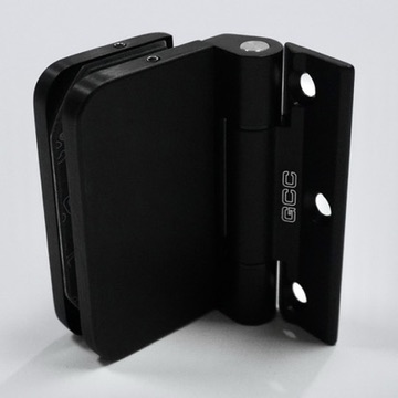
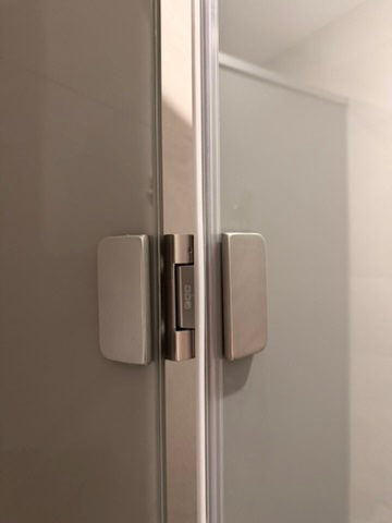
安裝尺寸 ①|後鈕(把手式鉸鏈)
取付寸法 ①|ヒンジ(レバーヒンジ)
Dimensions ①|Lever Hinge

開孔圖 ②|把手式門鎖(玻璃開孔)
穴あけ図 ②|レバーロック(ガラス穴あけ)
Drilling ②|Lever Lock (Glass Cut-outs)
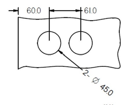
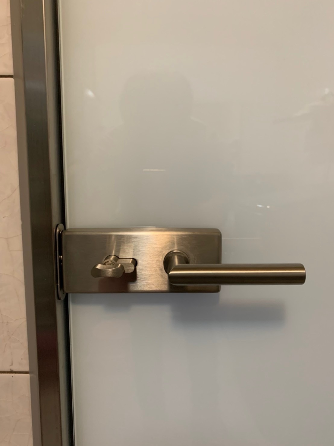
電控玻璃厚度 × 五金夾口對照
調光ガラスの厚み × 金物の挟み込み幅 対照
Smart Glass Thickness vs. Hardware Clamp Range
| STARTEK 玻璃厚度 | 對標準夾口 8 – 10 mm | 設計階段該做的事 |
|---|---|---|
| 8.6 mm | 在範圍內 | 可直接指定標準款五金 |
| 10.6 mm | 超出 10 mm | 須先向五金商確認:改 12 mm 訂製款,或確認墊片可否吸收差值 |
| 11.2 mm | 超出 10 mm | 建議直接指定 12 mm 訂製款 |
| 複層 / 特殊夾層結構 | 需個案確認 | 出圖前把實際總厚度送給五金商核算 |
| STARTEK ガラス厚 | 標準挟み込み幅 8 〜 10 mm との関係 | 設計段階で行うこと |
|---|---|---|
| 8.6 mm | 範囲内 | 標準品の金物をそのまま指定できます |
| 10.6 mm | 10 mm を超過 | 金物商へ事前確認が必要:12 mm の特注品に変更するか、パッキンで差分を吸収できるかを確認します |
| 11.2 mm | 10 mm を超過 | 12 mm の特注品を直接指定することを推奨します |
| 複層 / 特殊な中間層構成 | 個別確認が必要 | 作図前に実際の総厚みを金物商へ送り、確認を取ってください |
| STARTEK glass thickness | vs. standard 8–10 mm clamp | What to do at design stage |
|---|---|---|
| 8.6 mm | Within range | Standard hardware can be specified directly |
| 10.6 mm | Exceeds 10 mm | Confirm with the hardware supplier: switch to the 12 mm made-to-order version, or verify that gaskets absorb the difference |
| 11.2 mm | Exceeds 10 mm | Specify the 12 mm made-to-order version |
| Laminated / special build-ups | Case by case | Send the actual total thickness to the hardware supplier before releasing drawings |
設計與施工注意事項
設計・施工上の注意事項
Design & Installation Notes
- 先開孔、後強化。凡需在玻璃上開孔的五金(鎖座、拉手,以及需開孔的鉸鏈型號),孔位都必須在玻璃強化前完成加工,強化後不可再鑽孔或切割。孔位一旦標錯,只能整片重做。
- 孔位周邊要覆蓋。凹口 / 孔 / 切口周圍 10 mm 內可能出現不可電控的透明區、氣泡或視覺失真,請以五金座本體或收邊覆蓋(見第 4 章「加工注意」)。四周的透明無效邊另見第 3 章。
- 門扇重量要先算。玻璃概算重量 ≈ 面積(m²) × 厚度(mm) × 2.5 kg。標準兩支鉸鏈的承重上限是 60 kg,超出時請與五金商確認是否加設第三支鉸鏈或改用高承重款。
- 電控門扇的出線。會開合的門扇不能讓電線裸露在鉸鏈側被反覆彎折;有框開關門的做法(門框與門斗框預埋電源保護管、電線自天花板落下)見第 6 章「有框開關門 安裝施作」。無框淋浴門若要做電控,請於設計初期就與 STARTEK 討論走線路徑。
- 正式開孔圖以五金商核發者為準。本章數值依原廠圖面轉繪,供設計階段定位使用;實際下料前請向五金商索取對應型號、對應飾面的正式開孔圖,並與玻璃加工圖對照確認。
- 穴あけを先に、強化を後に。ガラスへの穴あけが必要な金物(錠座、プルハンドル、および穴あけが必要なヒンジ型番)については、孔位置をすべてガラスの強化前に加工してください。強化後は穴あけも切断もできません。孔位置を一度誤ると、1 枚まるごと作り直しとなります。
- 孔の周囲は覆ってください。切欠き / 孔 / スリットの周囲 10 mm 以内には、調光しない透明領域、気泡、視覚的な歪みが生じる場合があります。金物の座本体または見切りで覆ってください(第 4 章「加工上の注意」参照)。四周の透明な不動作エッジについては第 3 章をご参照ください。
- 扉の重量を先に算出してください。ガラスの概算重量 ≈ 面積(m²) × 厚み(mm) × 2.5 kg。標準のヒンジ 2 本の耐荷重上限は 60 kg です。これを超える場合は、3 本目のヒンジを追加するか高耐荷重品に変更するかを金物商にご確認ください。
- 調光する扉の配線取出し。開閉する扉では、ヒンジ側で配線が露出して繰り返し折り曲げられることのないようにしてください。框付き開き戸の納まり(戸枠と方立枠への電源保護管の先行埋設、天井からの配線引き下ろし)は第 6 章「框付き開き戸の施工」をご参照ください。フレームレスのシャワードアで調光を行う場合は、設計初期の段階で配線経路について STARTEK にご相談ください。
- 正式な穴あけ図は金物商が発行するものを基準としてください。本章の数値はメーカー図面より作図したもので、設計段階での位置決めにご利用いただくものです。実際の加工前には、該当型番・該当仕上げの正式な穴あけ図を金物商へご請求のうえ、ガラス加工図と照合してご確認ください。
- Drill first, temper after. Every hole drilled into the glass — locks, pull handles, and hinge models that require drilling — must be machined before tempering. Toughened glass cannot be drilled or cut, so a mislocated hole means a replacement panel.
- Cover the zone around each hole. Within 10 mm of any notch, hole, or cut-out there may be clear non-switchable areas, small bubbles, or visual distortion — cover them with the hardware plate or trim (see Section 4, "Fabrication Note"). For the clear inactive border on all four edges, see Section 3.
- Calculate the leaf weight first. Approximate glass weight ≈ area (m²) × thickness (mm) × 2.5 kg. Two standard hinges carry up to 60 kg; above that, confirm with the supplier whether a third hinge or a higher-capacity model is required.
- Wiring a switchable leaf. A swinging leaf must not leave cabling exposed to repeated flexing at the hinge side. For framed swing doors — power conduit pre-embedded in the door and head frames, wires dropping from the ceiling — see Section 6, "Framed Swing Door Installation". For frameless shower doors, discuss the cable route with STARTEK at the earliest design stage.
- The supplier's drawing governs. The dimensions here are redrawn from factory drawings for design-stage positioning. Before fabrication, request the official drilling drawing for the exact model and finish, and cross-check it against the glass fabrication drawing.
淋浴間的對外窗要做電控?
シャワールームの外窓を調光にしたい場合
Switchable Glass on a Bathroom Exterior Window
- 二次線一樣要預留。換玻璃不代表可以省掉走線:電極仍須藏入窗框溝槽,二次線從電極穿過窗框出線孔走到變壓器,見第 6 章「框架設計/佈線規劃」。窗邊沒有預留出線路徑,玻璃換好也點不亮。
- 舊玻璃要拆,所以先確認舊玻璃尺寸。下單前先量到實際尺寸(含框內咬入量)再據以生產;等拆完才發現尺寸對不上,窗戶會開著空等。
- 先確認舊玻璃是單片還是中空複層。舊對外窗常見是 8 mm 單片玻璃;較新的對外窗才會做中空複層。原本是中空複層的,換成電控複層式後總厚度與構成不同,須先確認既有窗框吃不吃得下。
- 二次側配線は同様に先行手配が必要です。ガラスを交換するからといって配線を省けるわけではありません。電極は引き続きサッシの溝に納める必要があり、二次側配線は電極からサッシの取出し孔を通してトランスまで配線します。第 6 章「フレーム設計/配線計画」をご参照ください。窓まわりに取出し経路が確保されていなければ、ガラスを交換しても点灯しません。
- 既存ガラスを撤去するため、まず既存ガラスの寸法を確認してください。発注前に実寸(枠への飲み込み量を含む)を採寸し、それに基づいて製作します。撤去してから寸法が合わないと判明すると、窓が開いたまま待つことになります。
- 既存ガラスが単板か複層かを先に確認してください。従来の外窓は 8 mm の単板ガラスであることが多く、比較的新しい外窓で複層となります。もともと複層だった場合、調光の複層式に交換すると総厚みと構成が変わるため、既存のサッシに納まるかを事前にご確認ください。
- The secondary wire route is still required. Replacing the pane does not remove the wiring: the electrode still has to sit inside the frame groove, with the secondary wire running through the frame exit hole to the transformer — see Section 6, "Frame Design / Cable Routing". With no exit route at the window, the new glass cannot be powered.
- The old pane must come out — measure it first. Take the actual dimensions (including the depth held inside the frame) before ordering; discovering a mismatch after removal leaves the window open and waiting.
- Check whether the existing pane is monolithic or an insulated unit. Older exterior windows are commonly 8 mm monolithic glass; only newer windows tend to use insulated double glazing. Where the existing unit is double-glazed, the switchable insulated build-up differs in total thickness and composition — confirm the existing frame can accept it.
實景參考
実景参考
Reference Photos
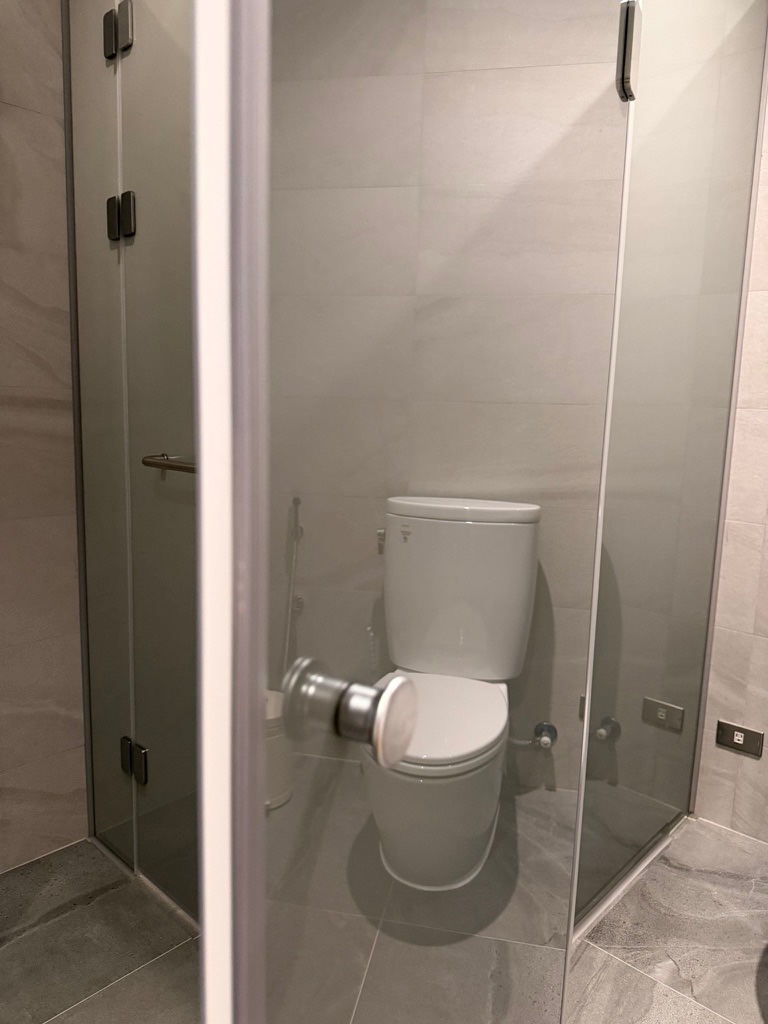
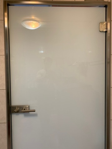
資料來源:GCC 官網 gccintw.com.tw(Lever Hinges and Ultra-silent Locks 產品頁)、GCC「Lever Hinges and Locks Type II」型錄、合作夥伴提供之開孔圖面,以及 STARTEK 案場實拍。本頁規格僅供設計階段參考,實際採購規格、開孔圖與報價請於下料前再次確認。
出典:GCC 公式サイト gccintw.com.tw(Lever Hinges and Ultra-silent Locks 製品ページ)、GCC「Lever Hinges and Locks Type II」カタログ、パートナー提供の穴あけ図面、および STARTEK の現場写真。本ページの仕様は設計段階のご参考です。実際の調達仕様、穴あけ図、お見積りについては、加工前に改めてご確認ください。
Sources: GCC official site gccintw.com.tw (Lever Hinges and Ultra-silent Locks), the GCC "Lever Hinges and Locks Type II" catalogue, drilling drawings supplied by our hardware partner, and STARTEK site photography. Specifications here are for design reference; confirm procurement specs, drilling drawings, and pricing before fabrication.